
Flying Saucers?
Page 1 of 3 • 1, 2, 3 ![]()

Re: Flying Saucers?
![]() by Cr6 Sat Apr 14, 2018 3:20 am
by Cr6 Sat Apr 14, 2018 3:20 am
The direction of "charge" on graphene can be set...similar to the copper sheeting to quickly focus charge:
https://milesmathis.forumotion.com/t123-mathis-on-graphene-any-hints#2150
(snippet)
Graphene Effectively Filters Electrons According to the Direction of Their Spin
December 26, 2013
New research from MIT shows that graphene can effectively filter electrons according to the direction of their spin, something that cannot be done by any conventional electronic system.
Graphene has become an all-purpose wonder material, spurring armies of researchers to explore new possibilities for this two-dimensional lattice of pure carbon. But new research at MIT has found additional potential for the material by uncovering unexpected features that show up under some extreme conditions — features that could render graphene suitable for exotic uses such as quantum computing.
The research is published this week in the journal Nature, in a paper by professors Pablo Jarillo-Herrero and Ray Ashoori, postdocs Andrea Young and Ben Hunt, graduate student Javier Sanchez-Yamaguchi, and three others. Under an extremely powerful magnetic field and at extremely low temperature, the researchers found, graphene can effectively filter electrons according to the direction of their spin, something that cannot be done by any conventional electronic system.
Under typical conditions, sheets of graphene behave as normal conductors: Apply a voltage, and current flows throughout the two-dimensional flake. If you turn on a magnetic field perpendicular to the graphene flake, however, the behavior changes: Current flows only along the edge, while the bulk remains insulating. Moreover, this current flows only in one direction — clockwise or counterclockwise, depending on the orientation of the magnetic field — in a phenomenon known as the quantum Hall effect.
In the new work, the researchers found that if they applied a second powerful magnetic field — this time in the same plane as the graphene flake — the material’s behavior changes yet again: Electrons can move around the conducting edge in either direction, with electrons that have one kind of spin moving clockwise while those with the opposite spin move counterclockwise.
...
From the Period 4 paper..more points from Miles that need to be remembered. I forgot completely his mentioning the Arsenic-Copper-Iron connection that Nevyn pointed out.
Miles Mathis wrote:I have now fielded a good question from a reader. He asks, “Don't you have charge being affected in opposite ways here? When channeled charge passes through the axis level, you say it interferes with conduction. But then you say it 'boosts' charge in Selenium. Isn't interference the opposite of boosting? How can that work?” It works because Selenium isn't conducting. You get conduction with elements like Arsenic and Copper, which have different numbers of protons top and bottom. Or you can get magnetic conduction with elements like Iron, but then you need more protons in the axis than in the carousel. Neither of those things is true of Selenium. Therefore, when the crossing charge meets the main axis charge in Selenium, it can only boost the charge. Some charge gets captured, you see, which acts like a boost. Remember, the interference I was talking about with conduction is actually a capturing of charge as well. But because it is captured by charge that is being conducted through the axis instead of charge being channeled into the carousel level, it ends up lowering the total instead of increasing it. Just think about it: we add an equal amount of charge to the top and bottom inner holes. So the north charge is increased by the same amount as the south charge. But the south charge was twice as strong as the north to start with (because the south has two protons pulling in charge while the north has one). Therefore, after adding equal amounts to both, the north charge is no longer half the south. It is a tiny bit more than half. Which means when they meet, we now get a tiny bit more cancellation. The north charge is a tiny bit stronger than it was, so it cancels a bit more than half of the south charge, giving us less conduction. But since Selenium isn't conducting, it doesn't feel experience this cancellation. It only experiences the boost. When elements have equal numbers of protons north, south and in the carousel level, the axis charge is pulled into the carousel level from the nuclear center, and so it never crosses.
http://milesmathis.com/per4.pdf
Cr6- Admin
- Posts : 1178
Join date : 2014-08-09 -

Re: Flying Saucers?
![]() by LongtimeAirman Sun Apr 15, 2018 4:02 pm
by LongtimeAirman Sun Apr 15, 2018 4:02 pm

Cr6, thanks for the help. My atomic understanding needs plenty of work. I’ve just reread the Selenium quote several times. Here’s my takeaway: 1. I believe that when“conduction” is used in this paragraph, it refers primarily to the main N/S charge flow within the atom; 2. Electric conduction occurs when the main N/S charge current through an element is unobstructed and there is an imbalance in the number of top and bottom protons which favors one predominant direction of charge current - such as we would find with Copper; 3. Magnetic conduction occurs when the main N/S charge current is unobstructed and there is an equal number of top and bottom protons - such as we would find with Iron; 4. Obstructed main channel charge flow occurs when protons occupy the hook positions – the locations of the four single protons in the Selenium diagram shown; 5. Charge traffic through the carousal level does not block the main N/S charge current; 6. Atoms capture charge from the field, Selenium hook position cross currents will add some charge to the main N/S charge current. Note. I’m no doubt missing several points and I’d greatly appreciate corrections.
With respect to the Lifter, I believe charge blockage is occurring between atoms sharing charge channels, between the individual air and Lifter atoms. For example, main upward charge channels from the air just below and entering the aluminum are redirected by the 30kV DC energization horizontally to the left or right, or perhaps in or out of the foil.
I believe this statement completely agrees with our charge field understanding, atoms are either matter or antimatter. Powerful magnetic field at extremely low temperature sounds a bit oxymoronic. It seems researchers are perfectly aware of electron spin and atomic polarity, and are adopting charge field ideas whatever their operating theory happens to be.Cr6 quoted. Under an extremely powerful magnetic field and at extremely low temperature, the researchers found, graphene can effectively filter electrons according to the direction of their spin, something that cannot be done by any conventional electronic system.
That is a perfect example of charge “blockage”, turning the charge thereby adding to the charge’s path length. Under high energetic conditions, with orthogonal magnetic field applied, charge current may be “turned” from vertical to horizontal, along the horizontal edges of the Lifters. A very nice possibility. With the Lifter, there’s no magnetic field. Can Al emit a magnetic field? What kind of current will the 30kV DC generate in the Al?Cr6 quoted. Under typical conditions, sheets of graphene behave as normal conductors: Apply a voltage, and current flows throughout the two-dimensional flake. If you turn on a magnetic field perpendicular to the graphene flake, however, the behavior changes: Current flows only along the edge, while the bulk remains insulating. Moreover, this current flows only in one direction — clockwise or counterclockwise, depending on the orientation of the magnetic field — in a phenomenon known as the quantum Hall effect.
At this point, I enjoyed and highly recommend the paper, Force on an Asymmetric Capacitor, by Thomas B. Bahder and Chris Fazi, http://jnaudin.free.fr/lifters/arl_fac/index.html, and found at http://jnaudin.free.fr/lifters/main.htm. The paper provides a good background – cleared for release or disposal. It has definitely added to my awareness.
From the Introduction:
The Biefeld-Brown Effect is expressed by the paper’s title - Force on an Asymmetric Capacitor.Biefeld-Brown effect, i.e., when a high voltage (~30 kV) is applied to the electrodes of an asymmetric capacitor, a net force is observed on the capacitor. By asymmetric, we mean that the physical dimensions of the two electrodes are different, i.e., one electrode is large and the other small. According to the classical Biefeld-Brown effect.
The paper includes background of the work done by Thomas Townsend Brown. Brown initially believed he had discovered an electromagnetic control of gravity. Brown had many followers, Fran De Aquino comes to mind. A few technical details.
the largest force on the capacitor is in a direction from the negative (larger) electrode toward the positive (smaller) electrode. … In fact, these experiments indicate that there is a force on the capacitor independent of polarity of applied voltage.
And a fine admittance of the lack of a theoretical explanation.
At the present time, there is no accepted detailed theory to explain this effect, and hence the potential of this effect for applications is unknown.
The authors built their own Lifters to verify the veracity of the device, including an aluminum covered Styrofoam lunch box and straws.
I’ll include a few more excerpts from the paper:
Furthermore, the force on the capacitor always appeared in the direction toward the small electrode—independent of the orientation of the capacitor with respect to the plane of the Earth's surface. The significance of this observation is that the force has nothing to do with the gravitational field of the Earth and nothing to do with the electric potential of the Earth's atmosphere. (There are numerous claims on the Internet that asymmetric capacitors are antigravity devices, or devices that demonstrate that there is an interaction of gravity with electric phenomena, called.)
I’m including the following because rather than saying the effect works in a vacuum or not, it would be good to know precisely when these effects are observed in order to, as they state, determine the effect’s possible usefulness in the future.
As discussed, the most pressing question is whether the Biefeld-Brown effect occurs in vacuum. It seems that Brown may have tested the effect in vacuum, but not reported it (Appendix B). More recently, there is some preliminary work that tested the effect in vacuum, and claimed that there is some small effect—smaller than the force observed in air; see the second report cited in reference [2]. Further work must be done to understand the effect in detail. A set of experiments must be performed in vacuum, and at various gas pressures, to determine the force versus voltage and current. A careful study must be made of the force as a function of gas species and gas pressure. In order to test the thermodynamic theory presented here, the dielectric properties of the gas must be carefully measured. Obtaining such data will be a big step toward developing a theoretical explanation of the effect. On the theoretical side, a microscopic model of the capacitor (for a given geometry) must be constructed, taking into account the complex physics of ionization of air (or other gas) in the presence of high electric fields. Only by understanding the Biefeld-Brown effect in detail can its potential for applications be evaluated.
Sorry for the prior JNL mistake, it should be jln Labs.
I’ll stop there.
.
Last edited by LongtimeAirman on Tue Apr 17, 2018 12:04 am; edited 1 time in total (Reason for editing : Quote Quote typo correction)
LongtimeAirman- Admin
- Posts : 2023
Join date : 2014-08-10
Re: Flying Saucers?
![]() by Cr6 Mon Apr 16, 2018 11:26 pm
by Cr6 Mon Apr 16, 2018 11:26 pm
Found a few things related.
https://www.upi.com/Science_News/2017/08/30/New-nano-sized-device-can-lift-165-times-its-weight/6331504120731/
...
http://www.gerbertechnology.com/news/first-unmanned-aerial-vehicle-takes-to-the-skies-during-farnborough-2016/
First Unmanned Aerial Vehicle Takes to the Skies during Farnborough 2016
Thursday, July 14, 2016•Categories: Laser Templating
WATERLOO, Ontario, Canada
Virtek Vision International, a market leader in the field of laser-based manufacturing technologies, announced lift off with the first unmanned aerial vehicle! A pioneering research collaboration between the University of Central Lancashire (UCLan) and The University of Manchester’s National Graphene Institute (NGI) will result in the world’s first public flights of Prospero, the first unmanned aerial vehicle (UAV) with graphene constructed wings.
The flights will take place at Farnborough Air Show 2016 July 15-17, 2016 between 2:00 p.m. and 2:30 p.m. GMT.
Carlos Pinto, sales territory manager for Virtek, said, “We are happy to be in partnership with the UCLan’s Engineering Innovation Centre (EIC) and their partners, demonstrating continuous innovation within aerospace using graphene. We are excited to see where this new material will go in benefiting aerospace carriers for future projects using graphene applications. On behalf of all of Virtek, congratulations on the hard work and progress you have made on this project and delivering innovation to aerospace.”
Virtek maintains a strong partnership with UCLan, continuing to innovate together in creating benefits to the manufacturing process in the aviation industry. Virtek Laser Projectors have the ability to guide a beam of laser light onto a work surface or part with a high degree of accuracy, speed and precision for applications such as composite ply layup, paint masking, placement of components or materials, and assists with assembly processes.
Billy Beggs, UCLan’s engineering innovation manager, said, “Graphene has huge potential for aerospace. It is incredibly strong, yet lightweight and flexible at the same time. Through our partnership with the National Graphene Institute at The University of Manchester, and alongside a number of Lancashire-based SMEs, we aim to develop a route map that enables graphene to play a key role in the future development of the aviation industry.”
Visit UCLan at the North West Aerospace Alliance, (NWAA) booth, Hall 1/B140, and visit with Virtek during Farnborough, Canada Area, Ontario Pavilion, Hall 4 E90.
Continue to connect with us @VirtekVision to hear more about “PROSPERO’s” next adventure. Also check out our new website: www.virtek.ca.
Photos accredited and provided by: University of Central Lancashire (UCLAN)
About Virtek
Virtek is the global leader in laser templating and quality inspection systems, providing exceptional expertise and engineering for manufacturers around the world. The Virtek name has become synonymous with precision, reliability, and innovation.
....
https://www.nanowerk.com/nanotechnology-news/newsid=38064.php
Posted: Nov 11, 2014
Graphene-toughened composites for next generation aerospace structures
(Nanowerk News) The School of Engineering at Cardiff University and Haydale have announced new research demonstrating significant improvements in mechanical performance including impact resistance in carbon fibre composites.
These results, particularly the increased damage tolerance, could have significant implications for the development of future composite structures, demonstrating the potential in future aircraft design for weight saving and the consequent environmental benefits such as reductions in CO2 emissions.
The research was undertaken by the Cardiff School of Engineering with additional funding from the European Community’s Seventh Framework programme under the Clean Sky Joint Technology Initiative. The Clean Sky Initiative is one of the largest existing European research programmes with the aim of accelerating technological advancements in aircraft design and green aviation technology. The project was based on requirements specified by the Centro Italiano Richerche Aerospaziale (CIRA) for developing new composite technologies for Green Regional Aircraft (GRA), and was managed by an integrated team from CIRA, Cardiff School of Engineering and Haydale.
....
Researchers unlock the secrets of dragonfly wings
21 August 2017 | Cordelia Sealy
From left to right: The dragonfly B. contaminata. The black rectangles on the wings show the parts of the wings investigated in this study, the nodus. (Top) SEM image of the nodus of the dragonfly. (Middle) Sketch of the nodus. (Bottom) CLSM image of the nodus. The blue color shows the resilin-dominated part.
From left to right: The dragonfly B. contaminata. The black rectangles on the wings show the parts of the wings investigated in this study, the nodus. (Top) SEM image of the nodus of the dragonfly. (Middle) Sketch of the nodus. (Bottom) CLSM image of the nodus. The blue color shows the resilin-dominated part.
Since humans have attempted to fly, we have tried to mimic the flapping action of birds and insects. Scientists have continued to design bioinspired micro-air vehicles (MAVs) with flapping wings, but there is a gap between the proficiency of even the most novel flying machine and the simplest insect. That gap can only be addressed by a better understanding of exactly how insect wings work.
Researchers from Kiel University in Germany and the Islamic Azad University in Iran believe that their approach can unlock the design principles of the wings of one of nature’s most remarkable aeronauts, the dragonfly [Rajabi et al., Acta Biomaterialia (2017), doi: 10.1016/j.actbio.2017.07.034].
“Dragonflies are known for their impressive flight performance,” says Hamed Rajabi of Kiel University. “They exhibit several flight styles and maneuvers of which many other insects are not capable.”
Although scientists have theorized about the origin of dragonflies’ superior flight capabilities, the role of each wing component in facilitating flight has remained elusive. Now Rajabi and coworkers are taking a new approach to untangling the structure-property-function of different wing components using a combination of wide-field fluorescence microscopy, confocal laser scanning microscopy, micro-computed tomography, scanning electron microscopy, numerical analysis and mechanical testing.
“Dragonfly wings are complex biological composite structures,” explains Rajabi. “At first glance, they appear to consist of two main structural components: an ultrathin membrane supported by reinforcing hollow veins. But, in more detail, they are a unique combination of further specialized components.”
https://www.materialstoday.com/biomaterials/news/researchers-unlock-the-secrets-of-dragonfly-wings/
...
Wing Manufacture
Many of today’s airplanes are made of carbon-fibre composite, but putting graphene in the carbon-fibre coating made the plane’s wings stronger.
It has better impact resistance and is lighter and more drag resistant than a comparable with conventional carbon-fibre wings. The material’s strength means the wings of the plane would need to be coated with only one layer of graphene-infused carbon fibre rather than four or five layers of the conventional composite. If you can build a stronger aircraft with less material, it’s lighter, and you’ll fly farther. In tests, a graphene-enhanced skin on the wings improved impact damage, a standard measurement of potential in-flight damage, by at least 60 percent.
Further advantages of graphene’s relatively high electrical conductivity remain to be tested. Conductivity protects a plane from lightning strikes, and because carbon fibre has low conductivity, current airplane wings usually include a copper mesh that provides this protection. In theory, this copper mesh could be eliminated if graphene is used in the wing, making the plane even lighter and more fuel efficient. Graphene’s conductivity also could be used to electrically de-ice a plane, according to a study released in ACS Applied Materials and Interfaces, thus eliminating the equipment costs associated with today’s chemical de-icing technology.
A thin coating of graphene nanoribbons in epoxy developed at Rice University has proven effective at melting ice on a helicopter blade. The coating by the Rice lab may be an effective real-time de-icer for aircraft, wind turbines, transmission lines and other surfaces exposed to winter weather, according to a new paper in the American Chemical Society journal ACS Applied Materials and Interfaces.
Further reading:
https://phys.org
https://www.sciencedaily.com/releases/2016/11/161128084523.htm
Cr6- Admin
- Posts : 1178
Join date : 2014-08-09 -
Re: Flying Saucers?
![]() by LongtimeAirman Tue Apr 17, 2018 12:01 am
by LongtimeAirman Tue Apr 17, 2018 12:01 am
Hi Cr6, I see you've recently posted some new subject matter. I'm still on the Lifter.
Repeating the end of the final quote of my previous post. From - Force on an Asymmetric Capacitor, by Thomas B. Bahder and Chris Fazi, http://jnaudin.free.fr/lifters/arl_fac/index.html.
A challenge! A model must be constructed. Given the charge field, easy, I thought. I had every expectation of using the ideas I’d shared with Cr6; but the first observation from the previous excerpt I’d quoted finally sunk in.On the theoretical side, a microscopic model of the capacitor (for a given geometry) must be constructed, taking into account the complex physics of ionization of air (or other gas) in the presence of high electric fields. Only by understanding the Biefeld-Brown effect in detail can its potential for applications be evaluated.
All my thinking up till now has been assuming that the Lifter force has been upward, toward the small electrode, in line with the Earth charge emissions from the Earth directly below. For example, my previous comment, “main upward charge channels from the air just below and entering the aluminum are redirected by the 30kV DC energization horizontally to the left or right, or perhaps in or out of the foil” is wrong. My model needs improvement.Furthermore, the force on the capacitor always appeared in the direction toward the small electrode—independent of the orientation of the capacitor with respect to the plane of the Earth's surface.
Below, I’ve modified the image below to include its source and title. http://jnaudin.free.fr/lifters/docs/UnconventionalScience.pdf.

Electrostatic Field around Lifter Electrodes. The electrostatic field around – looking down along - two Lifter electrodes are shown. The wire appears as a circle just below the center of the image, about the size of the period at the end of this sentence. The aluminum foil covers the rounded top and one of the two - right or left - sides of the thin white rectangle below the wire. Both the wire and aluminum foil are perpendicular - in or out - to the image. The energized electrostatic field shown is oriented with respect to the electrodes and is the same regardless of the direction of the Earth - up may be in any direction.
The image is a slice, or cross section, and an easy way to compare the asymmetric surface areas (line lengths in this diagram) of the thin wire and a two sided wide strip and a rounded top surface edge of the aluminum foil. The foil electrode is charged at its highest energy level, 30kV DC, the top red color shown on the energy scale on the right edge of the image. The wire is at the bottom of the energy scale shown. The separation distance between the electrodes has been chosen to avoid arcing - a breakdown of the air, where sparks bridge the gap between the electrodes - at the desired operating voltage. Two of the three sides of a Lifter may be thought of as coming together in the white rectangle, with little to no interference at the Lifter’s 60 degree corners. I believe the lines of constant electrostatic strength, the wide lodes to the right and left are an accurate representation of the extent and degree of ionization present in the air around and between the electrodes.
I was wrong to believe the important boundary was the bottom air/foil interface (bottom edge center zero mark). I now believe, as the image nicely conveys, the important boundary is the foil/air interface between the electrodes, including the electrostatic charge strength of the ionized air to the sides of the energized foil. The foil is emitting a very high B-photon emission rate in sufficient quantity to ionize the air to the various energization levels shown. This is a demonstration of charge path lengthening, it appears most charge is emitted far to the sides of the foil instead of directly toward the wire. There is a relative charge vacuum at the wire. The result is a slow net motion of the electrodes in the direction of the small electrode regardless of the direction of the Earth’s emission field.
Yeah, Nay? I'll move on, but I'd prefer your ideas to help make this Lifter idea agreeable to all of us.
.
LongtimeAirman- Admin
- Posts : 2023
Join date : 2014-08-10
Re: Flying Saucers?
![]() by Jared Magneson Wed Apr 18, 2018 3:48 am
by Jared Magneson Wed Apr 18, 2018 3:48 am
Really cool stuff.
Jared Magneson- Posts : 525
Join date : 2016-10-11
Re: Flying Saucers?
![]() by Cr6 Wed Apr 18, 2018 8:29 pm
by Cr6 Wed Apr 18, 2018 8:29 pm
http://phys.org/news/2010-12-graphene-pencil-sticky-tape-videos.html
Cr6- Admin
- Posts : 1178
Join date : 2014-08-09 -
Re: Flying Saucers?
![]() by LongtimeAirman Wed Apr 18, 2018 10:27 pm
by LongtimeAirman Wed Apr 18, 2018 10:27 pm
Thanks for the “Yeah” Jared. Acknowledging what I’d hoped was a legitimate charge field interpretation for the Lifter. However, your words indicate a misunderstanding I’d be remiss to ignore. I don't want you or Cr6 accidentally hurting yourselves. You can re-vote after I describe: 1) the Lifter; 2) the Lifter and the upward charge of the Earth; and 3) the Lifter and a horizontal aluminum foil electrode - in slightly more detail.Jared wrote. Yeah, it seems like (to me, obviously) that the Lifter would work better if the aluminum foil were draped across horizontally it in terms of catching upward charge from the Earth.

J Naudin agrees with the need for a large horizontal electrode orientation in the image above, although I’m not at all sure which way the small electrode lies (360 Degrees?).
With respect to Lifter, the Earth’s emission field holds up the air and creates the ambient background energy level; beyond that, in my charge field estimation, the Earth’s emission field may be disregarded. The Lifter electrodes emit a strong local electrostatic field that overwhelms Earth’s much weaker emissions; I suppose the Lifter reaches a neutral buoyancy in the air. At which time the asymmetric imbalance of the electrodes and direction of charge emitted by the Lifter allow the demonstration of the Biefeld-Brown effect - a force in the direction of the smaller electrode. The Lifter operates within a given Earth emission field. The Lifter is said to exhibit a force toward the smaller electrode regardless of the direction of the Earth. We do not want to catch additional charge from the Earth, all the effective lift is caused by a local asymmetrical high voltage field.
Modifying the Lifter design to rotate the foil electrode from a vertical to a horizontal orientation directly below the wire will lose the Biefeld-Brown effect. Recall in the electrostatic field image that most of the aluminum foil emissions occur perpendicular to the foil – left or right - away from the foil, at the same time increasing distance away from the small wire electrode above. Rotating the foil 90 degrees would point the foil’s majority perpendicular B-photon emissions directly toward the small wire electrode. The resulting direct charge flow would mean that arcing would be a problem. The electrodes would require a greater separation distance. Most importantly, if charge is not turned or blocked, there’s no charge lift.

http://jnaudin.free.fr/lifters/liftercraft/index.htm
J. L. Naudin, T. T. Brown, Fran De Aquino, and apparently Tesla too, all believed that gravity could be controlled electromagnetically. That is a false notion, we cannot control gravity. We may, however, control charge in limited ways.JNaudin wrote. I am currently in search of sponsors to finance this project.
Thanks for the help.
.
LongtimeAirman- Admin
- Posts : 2023
Join date : 2014-08-10
Re: Flying Saucers?
![]() by Jared Magneson Wed Apr 18, 2018 11:06 pm
by Jared Magneson Wed Apr 18, 2018 11:06 pm
Jared Magneson- Posts : 525
Join date : 2016-10-11
Re: Flying Saucers?
![]() by LongtimeAirman Fri Apr 20, 2018 2:45 pm
by LongtimeAirman Fri Apr 20, 2018 2:45 pm
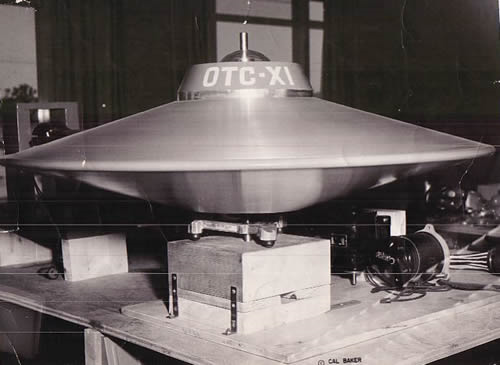
http://myfavoritecrafts.com/385249-otc-x1-space-crafts.html
Let’s look at a Flying Saucer I was told makes regular runs to the planets. Going back to the prototype, about 1958 designed by Otis Carr. I've assembled some images. If you know a better source, please share.

http://hello-earth.com/otistcarr/otistcarr.html

http://hello-earth.com/otistcarr/interviewotistcarr15november1958part1.htmlCircular Foil Spacecraft
Utron Electrical Accumulator
Using Space itself as the catalyst for the
interchangeable forces of electromagnetism and gravity
The hello-earth site has three recorded interviews with Otis Carr. I haven’t heard them, I’m satisfied with the transcriptions.
/////////////////////////////
Otis Carr – Technical
https://everipedia.org/wiki/otis-carr-technical/
Otis T. Carr has some information in the public domain for anyone who may be technically minded or interested in furthering Carr's research. As a protégé of Nikola Tesla much of Carr's theory, dynamics and mechanics re gravity / anti-gravity are Tesla-based.

According to Carr:
"Any vehicle accelerated to an axis rotation relative to its attractive inertial mass, immediately becomes activated by free-space-energy and acts as an independent force... We have shown that a charged body, accelerated to an axis rotation relative to this attractive inertial mass, indicates polarity[3] in a given direction.
The dip-needle points, say, up toward the top of the body. But mount this while rotating body, with its spindle, on another platform and rotate this platform on a spindle, then if the counter-rotation is greater than the inertial forward rotation of the body, a dip-needle on the second platform will point down while the first dip-needle points up, indicating complete relativity of polarity. When the exact counter-rotation matches the forward rotation the body loses its polarity entirely and immediately becomes activated by free-energy (tensor stresses in space) and acts as an independent force... The above-described assembly of counter-rotating charged masses becomes weightless and will escape the immediate attraction of gravitational forces."

/////////////////////////////
I’ll try to give the OTC-X1 a Charge Field assessment.
.
LongtimeAirman- Admin
- Posts : 2023
Join date : 2014-08-10
Re: Flying Saucers?
![]() by Ciaolo Sat Apr 21, 2018 3:58 am
by Ciaolo Sat Apr 21, 2018 3:58 am
by vehicle he means this saucer, right? What is the acctractive inertial mass? How can we say if an axis is relative to it?Carr wrote:"Any vehicle accelerated to an axis rotation relative to its attractive inertial mass,
The vehicle acts as a force? What does it mean?
immediately becomes activated by free-space-energy and acts as an independent force...
By indicates polarity he means we can see the effects of a N/S magnet?
We have shown that a charged body, accelerated to an axis rotation relative to this attractive inertial mass, indicates polarity[3] in a given direction.
The platform has to always be in contact with the body for it to be weightless? If not, this effect could have no need for the rotating platform.
The dip-needle points, say, up toward the top of the body. But mount this while rotating body, with its spindle, on another platform and rotate this platform on a spindle, then if the counter-rotation is greater than the inertial forward rotation of the body, a dip-needle on the second platform will point down while the first dip-needle points up, indicating complete relativity of polarity. When the exact counter-rotation matches the forward rotation the body loses its polarity entirely and immediately becomes activated by free-energy (tensor stresses in space) and acts as an independent force... The above-described assembly of counter-rotating charged masses becomes weightless and will escape the immediate attraction of gravitational forces."
Ciaolo- Posts : 143
Join date : 2016-09-08
Re: Flying Saucers?
![]() by LongtimeAirman Sun Apr 22, 2018 2:40 pm
by LongtimeAirman Sun Apr 22, 2018 2:40 pm
Ciaolo wrote. Please help, I want to understand but I’m confused... this looks very important. The platform has to always be in contact with the body for it to be weightless? If not, this effect could have no need for the rotating platform.… When the exact counter-rotation matches the forward rotation the body loses its polarity entirely and immediately becomes activated by free-energy (tensor stresses in space) and acts as an independent force... The above-described assembly of counter-rotating charged masses becomes weightless and will escape the immediate attraction of gravitational forces..."
Airman. Ciaolo, I must apologize, I’m in a bit of a quandary myself. Armed with Miles’ papers and charge field perspective, I’m absolutely certain we can understand physical problems better than mainstream. Go ahead, point anywhere and I’ll prove it, just find an interesting subject and we’ll give it go. Real physical details are best, Otis T. Carr’s OTC-X1 turned out to be a scam. I don’t know what, if anything, about it is real.
Here a few of the “facts” I’ve learned are claimed about the operational saucer. It required a blue crystal and was driven by mind control. It travels instantly between planets or wherever you would wish it to go. An advanced technology - Utrons - provide power without wires. The operational vehicles were confiscated by the military. The diagrams I’d provided above were said to have been converted to an amusement park ride in order to make it past a Patent Office ban against flying saucer designs. Otis Carr collected a large sum of money from investors for which he was later convicted.
Another good site for OTC-X1 info, http://www.rexresearch.com/carr/1carr.htm
Interview: "Long John" Nebel (WOR Radio, NY) with Otis Carr, et al. (1959) ---
OTC (Otis T. Carr): "Our system utilizes gravity, electromagnetism, and electromotive force and a relative field to get its functional operation. We use an electrified sender. It's a sensor power core. Now this is what we call an accumulator... It is a storage cell, an accumulation of storage cells which provide an electromotive force in the same manner that any known battery produces and electromotive force...
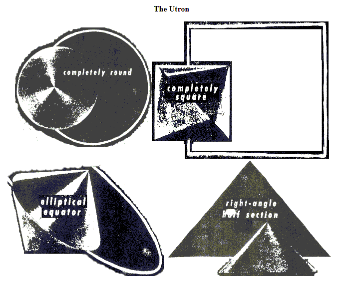
I'm sorry, I cannot take anything he says seriously. If Otis was a con man he could spout jargon with the best of them. I’d be more than happy to examine something of value here, but I’m not seeing it.This [the Utron] is a dimensional product. It was designed with the dimensions of space itself. We say it is truly the geometric form of space, because it is completely round and completely square. It has been proven in scientific laboratories that the very smallest unit of mass matter ever photographed in the electron microscope are square in shape... We have applied this principle into an electrified system, which is the power core of our space vehicle. Now what makes this unique and novel from a battery is the fact that this is a piece of moving machinery that rotates. Our average storage battery is an inanimate object set in an inertial spot and then the electromotive force is conducted by wires from this battery to animate some object.
The OTC-X1 is a bust.
.
LongtimeAirman- Admin
- Posts : 2023
Join date : 2014-08-10
Re: Flying Saucers?
![]() by LongtimeAirman Sun Apr 22, 2018 5:11 pm
by LongtimeAirman Sun Apr 22, 2018 5:11 pm

Moving on. With respect to rotation as a velocity orthogonal to the Earth’s emission field, you may recall I mentioned discs. I’m afraid Jared’s interest in a charge field lift theory for helicopters may be way too complicated for me to even begin to figure out - discs are much easier to grasp
Full disclosure, I love disc. I played Ultimate Frisbee for most days every week for a few years. My specialty was tossing long hang time discs - leading a running target in all kinds of weather. I miss the team. I haven’t watched any sports since ESPN decided not to show a particular Ultimate competition over twenty five years ago.
I grabbed a document describing disc physics from the intertoobs, looks like it could use a charge field review. First I’m posting it in its entirety. Corrections will hopefully follow. With all due respect, please consider,
The Physics of Disc Flight.
Australia Flying Disc Association, Ultimate Australia
https://afda.com/the-physics-of-disc-flight
A flying disc is a little like a cross between a gyroscope and a wing.
A wing works by having the top and bottom sides of different lengths. The air flow moves over the longer surface faster, creating a low pressure region on top of the wing. The higher pressure region underneath the wing tries to move toward the low pressure region, and as a result lifts the wing.
A disc is like a gyroscope in that it uses gyroscopic inertia, the tendency of a gyroscope to keep spinning in the same plane without twisting and turning.
With no spin, a disc is inherently unstable, and with no speed, no lift is generated, so a combination of these factors is needed for a disc to fly. The exact combination varies significantly from disc to disc, since different discs have different "wing" shapes. Combining the wing and the gyroscope also introduces other factors, as the two are not mutually independent.
The most obvious one is a torque on the disc. If the disc is spinning clockwise and moving forward when viewed from the top, then the left side of the disc is moving faster than the right side. There is a corresponding pressure drop over the left side and that side will produce greater lift, and the disc will try to twist clockwise when viewed from behind. As mentioned above, the gyroscopic inertia acts to counter this, and the greater the spin, the higher the inertia.
Spin
There is almost never any reason for not trying to put as much spin as possible on a disc, all other factors being equal. Spin provides stability, so that the disc will continue to fly in the direction it is already flying. A disc that is lacking in spin will tend to "turn over", that is, twist about the axis of flight, and will generally not go as far as one which has more spin. Lack of spin is probably one of the two major problems encountered when trying to throw accurately over any reasonable distance.
One time when too much spin is possible is when throwing some golf discs. Their flight characteristics are such that they have a very narrow window of stability. Too much spin and they can twist one way, and too little spin and they will twist the other. In general, however, too much spin is better countered by other factors in the throw, such as speed and angle of release, rather than by simply spinning the disc less.
Particular discs are termed "overstable", "stable", and "understable" depending on how they to spin and speed. A disc which needs a lot of spin to be stable at a given speed is called "understable", while a disc which needs little spin to be stable at a given speed is called "overstable". "Stable" generally refers to discs which are stable at a wide range of speeds for a given spin.
Most discs can be thrown "understably" or "overstably" by decreasing or increasing the amount of spin put on the disc.
Speed
The speed of a disc is a major (but not the only) factor in determining how far a disc goes and how quickly it gets there. Unlike spin, it is possible to put too much speed on a disc. The stability of a disc changes as it gets faster, and the stable range of the disc is determined both by the shape of the disc and its spin rate. Most discs used for throwing to other people are stable, that is, they fly flat at a range of speeds. Golf discs on the other hand are usually not very stable - they tend to fly flat only for brief periods during their flight. The rest of the time they are banked either one way or the other.
A generally stable disc thrown with too much speed in relation to the spin will act understably. That is, it will turn over. For this reason, hucking the disc requires plenty of spin and speed. Not enough speed results in the throw landing short, while not enough spin results in the throw diving into the ground.
Most inexperienced players find it easier to get more spin on their backhand, and as a result most inexperienced players will huck on their backhand side.
Rotation Angle
The title does a poor job of explaining what this section is about. Apart from amount of spin, the other major factor in lack of accuracy and distance is the difference between the angle of spin of the disc and the angle of the plane of the disc. The disc often wobbles at the start of its flight, and this is the problem. Ideally, the disc should be spinning flat and wobble-free. If the thrower puts spin on the disc at an angle to the flat plane of the disc, it will wobble and lack control.
This is usually most obvious when teaching beginners the air bounce. For an air bounce, the disc is being thrown downwards, and at release the thumb is dragged across the trailing edge of the disc. This results in a slow upward flight. The thrower’s wrist is at a sharp angle to their arm, and beginners often find that getting the arm to move one way while spinning the disc with their wrist in another direction entirely is very difficult.
The end result is a wobbly throw that lacks spin in the right direction, and hence lacks both stability and the ability to get much distance. Similar problems usually result when teaching the high release backhand.
There is often no easy solution. In the case of air bounces and high release backhand the cure is generally practice. The wrist needs time to learn that it can impart spin at a different angle to that of the arm. In the case of normal throws, the thrower may be swinging the disc in a loop instead of straight back and then straight through. The trick may be just to get them moving the disc straight back on the backswing and straight through on the follow through. This is often harder to do than it sounds. Also, it may not be the problem. Plenty of good players use a slightly loopy backswing, but they are able to get their wrist and arm in the right line just before release, usually just through practice.
Attitude (Pitch)
Here we are borrowing a term from aviation to describe one of the angles of release. Pitch refers to how steeply an aircraft is pointed, rotating about an axis through the wings. For a disc, it refers to the angle of release where the front edge of the disc is pointed up or down. Basically the pitch helps determine how far the disc travels, and more importantly, along which path. By keeping the front edge well up the disc will travel well into the air, but will probably stall and float down at the end of the flight. Keeping the front edge down results in a low trajectory, relatively fast flight.
Roll (Bank)
Roll, or bank, refers to the angle of the disc rotated about the direction of travel. This means whether the outside edge of the disc is held up or down. The amount of bank on the disc mainly determines the flight path, and can be used to good effect to throw around players who are between thrower and target. The disc will curve in the direction of the lowest edge of the disc.
Wind
Wind can have a marked effect on all of the five factors mentioned above, depending mostly on which direction it is coming from. An important point to remember is that regardless of how much wind there appears to be, there is no wind at ground level, and there is less wind the closet to the ground you are. This means that to avoid the effects of the wind as much as possible it is a good idea to release and keep throws as close to the ground as practicable.
A headwind increases the apparent air speed of the disc. This means that the amount of spin necessary to keep it stable becomes greater. A headwind also reduces the distance possible, and lifts under discs that are pitched with the leading edge up, sending them into the air.
A tailwind conversely decreases the air speed of the disc, but can increase ground speed. While distance may increase there is a drop in lift, which means that the disc needs to be thrown at a higher angle of attack to counteract the wind that tends to push the disc into the ground.
Crosswinds have the most effect on banked discs, either by pushing the raised edge up and lifting the disc, or by pushing down on a lowered edge and possibly making the disc dive into the ground. Crosswinds also make it difficult to keep the disc flat on release, and even experienced players may find it difficult to keep the angle of spin in the plane of the disc.
.
LongtimeAirman- Admin
- Posts : 2023
Join date : 2014-08-10
Re: Flying Saucers?
![]() by LongtimeAirman Wed Apr 25, 2018 7:23 pm
by LongtimeAirman Wed Apr 25, 2018 7:23 pm
OTC-X1 note. I ended my review rather abruptly. I'll try to do a better job here. You probably noticed my main interest is in the Utron, the OTC-X1 “power supply”. Not because it is both square and round - and painful for me to hear O.T.C. describing it so - but because it spins. A large utron mounted with a vertical spin axis will suck in Earth’s vertical emissions at its spin axis and turn that charge horizontally outward – thus creating charge lift. In the amusement ride, the central Utron is absent, replaced with a large vertical (expandable (?)) column, along with any lift it might have created. Without further details, such as wiring, the utron looks like a low friction free mounted flywheel.
Then there are the two outer horizontal counter-rotating frames with: 12 each copper coils and iron cores (electromagnets), 6 smaller utrons, 6 large capacitor plates and supporting structure. These rotating structures must also turn upward charge outward and so cause charge lift, although the utrons, capacitors and electromagnets may greatly alter the nature of the overall energized charge field. The Lifter worked because the entire lifter is energized as an asymmetric capacitor; the distributed electromagnetic components in the OTC-X1 would leave the entire structure subject to the Earth’s charge field alone. By the way, I failed to mention that images I linked to showed copper coils being wired in place – granted, a very difficult task - with such poor craftsmanship, I believe the thing could never have “worked”. No surprise if they didn’t make it to the moon, the amusement ride also seems to have been a bust.
All I see is a public relations fantasy with no substance. Rational description and substantiated claims are lacking, or I’m missing them. If you know of any significant claims I haven’t mentioned or that I should pay closer attention too, please feel free to share.
//////////////////////////////////////////////////////////////////
Back to Flying Discs. Reviewing The Physics of Disc Flight. Australia Flying Disc Association, Ultimate Australia. https://afda.com/the-physics-of-disc-flight
A flying disc is a little like a cross between a gyroscope and a wing.
I must add. “A disc moves with both a forward velocity, as well as a tangential spin velocity”.
In Billiards, a struck cue ball is given an initial velocity, direction, and spin. Likewise, a flying disc is thrown with initial nose and attack angles, velocity and spin. Like the soft surface of a billiard table slows the cue ball’s motion to just a few cushion rebounds, the air slows the flying disc to just a few tens of meters before it hits the ground.
In his Lift paper, Miles quickly dispenses with the common belief that unequal top and bottom path lengths cause lift by pointing out there’s no reason for air separated by the wing to rejoin at the same place. I may also point to the fact that one may throw a disc “upside-down” without worrying about unequal path lengths accelerating discs downwards to the earth.
Replace the lined-out above with a portion of Miles’ quote at the top of the thread. (From Lift).
The only way to increase the charge lift is to increase the charge, but since the charge is constant in each area during each interval, the only way to increase charge is to go into as many different areas during the same interval as you can. In other words, you have to move fast, and you have to move perpendicular to the field.
A disc is like a gyroscope in that it
Replaced "uses gyroscopic" with "creates a spin".
With no spin, a disc is inherently unstable, and with no speed, no lift is generated, so a combination of these factors is needed for a disc to fly. The exact combination varies significantly from disc to disc, since different discs have different "wing" shapes. Combining the wing and the gyroscope also introduces other factors, as the two are not mutually independent.
Good to know. So, in the case of flying discs, spin is necessary. How much spin would that be? I offer the observation that a disc’s spin is the same as the disc’s roll rate. For example, if I throw the disc low to roll edgewise along the ground, tilted over a bit like a sail, the disc rolls forward at the same velocity and spin rate as another disc flying through the air just above it. The disc need rotate roughly once for each circumference of forward distance traveled.
The most obvious one is a torque on the disc. If the disc is spinning clockwise and moving forward when viewed from the top, then the left side of the disc is moving faster than the right side. There is a corresponding
Replaced "pressure drop over" with "charge lift increase felt by".
If spinning can contribute an eighth of the total charge lift a disc received, where is that charge lift felt? In the example given, that would be the left side of the disc which is moving at twice the disc's forward velocity (or ground velocity); the right side of the disc is traveling at zero velocity. Experienced players always release the disc with nose and attack angles specifically allowing for the “
I do not agree that gyroscopic inertia would counter the so called "
The rest of the document covers technique, I agree with all the remaining comments made in The Physics of Disc Flight.
Your comments are welcome.
.
Last edited by LongtimeAirman on Wed Apr 25, 2018 11:17 pm; edited 2 times in total (Reason for editing : Changed and added to sentence ending in zero velocity.)
LongtimeAirman- Admin
- Posts : 2023
Join date : 2014-08-10
Re: Flying Saucers?
![]() by LongtimeAirman Thu Apr 26, 2018 10:21 pm
by LongtimeAirman Thu Apr 26, 2018 10:21 pm
Frisbee Flying Discs - continued.
As Miles states in the Lift paper, the Charge lift felt by an object – say a wing, is determined by the wing’s orthogonal velocity with respect to the earth’s vertical charge emissions. The same definition also applies to Frisbee throwing discs. The disc’s motion is slightly more complicated than a wing’s, in addition to motion forward, the disc is also spinning. For the flying disc, the orthogonal velocity is determined by the sum:
Orthogonal velocity = linear forward velocity + tangential spin velocity.
Consider tangential spin alone, let forward velocity equals zero. Each atom within a spinning disc will travel at different velocities determined by their radial position in the disc. The least tangential spin velocity occurs at the disc’s center and the maximum tangential spin velocity occurs at the spinning disc’s edge. Charge lift due to tangential spin velocity alone occurs primarily near the spinning disc’s edge. Without a finger to rest on, the spinning disc will fall downward, maintaining its vertical spin axis, slower than one gravity, probably due to a stable spin and some air resistance.
Now include both linear forward velocity and tangential spin velocity. I’m afraid vector addition is required. I’ll assume that there is one rotation per every circumference of forward distance traveled. In that case, I believe the tangential velocity = the forward velocity = v. Such throws maintain their lifts very well. Given a RHBH (right hand back hand) throw – the disc spins clockwise as it travels forward. Let’s look at the orthogonal velocities of a few of the disc’s locations in detail.
1) 1200, the leading front edge of the disc. The tangential spin velocity at the 1200 position is to the right, orthogonal to the forward velocity yet still orthogonal to the earth’s emission field. The vector sum points in a direction 45 degrees to the right of the forward direction. I believe the magnitude of the resulting orthogonal velocity is given by: Orthogonal velocity = sqrt[forward velocity^2 + tangential velocity^2] = sqrt[2* forward velocity^2 ] = 1.41*forward velocity = 1.41v.
2) 0300, the right edge of the disc. The 0300 position is rotating clockwise, back towards the thrower, opposite to the forward direction. The tangential spin velocity = - forward velocity. Orthogonal velocity = linear forward velocity + tangential spin velocity = forward velocity - forward velocity = 0v.
3) 0600, the disc’s back edge, closest to the thrower. As in the 0000 case, the tangential spin velocity is at right angles to the forward velocity, this time in the opposite direction, to the viewer’s left. As in the 0000 case, I believe that we are concerned with only the magnitude (and not the direction) of the vector addition giving the same magnitude orthogonal velocity. Orthogonal velocity = sqrt[forward velocity^2 + tangential velocity^2] = sqrt[2* forward velocity^2 ] = 1.41*forward velocity = 1.41v.
4) 0900, the left edge of the disc. The 0900 position is traveling at forward velocity plus tangential spin velocity. That edge of the disc is traveling at the highest total velocity and so it will receive the largest share of charge lift. Orthogonal velocity = tangential spin velocity + forward velocity = 2*forward velocity = 2v.
5) Center of disc. Tangential spin velocity = 0. Orthogonal velocity = forward velocity = v.
As I’ve shown above, the least amount of orthogonal velocity, and zero charge lift occurs at 0300; the most charge lift occurs at at 0900. A RHBH throw develops the highest charge lift along its left edge; a well thrown RHBH disc will slowly rotate in a clockwise (when viewed from behind) direction. A well thrown LHBH – left hand back hand - thrown disc will slowly rotate in a counter-clockwise rotation for the same reasons and at the same rate. In my opinion that is true disc behavior, another confirmation of charge theory.
That rule works over the majority of the thrown disc’s path traveled, the disc loses energy and drops before too long. The initially vertical disc spin axis slowly turns CW, at some point, the spin axis will rotate to a sufficiently horizontal direction where the disc may accelerate into the dirt. Each toss involves various choices and skills, beginning with the disc.
To give the reader a flavor of disc performance - pertaining to variations in charge lift generation capacities, what little there may be, I’ll merely point out a typo and suggest a correction in the The Physics of Disc Flight. The third paragraph and final sentence in the Spin section:
Particular discs are termed "overstable", "stable", and "understable" depending on
Most discs can be thrown "understably" or "overstably" by decreasing or increasing the amount of spin put on the disc.
I replaced “how they to spin” with “how quickly they react to spin”. I believe quickly refers to the how quickly the disc rotates CW or CCW in reaction to the uneven charge lift.
.
LongtimeAirman- Admin
- Posts : 2023
Join date : 2014-08-10
Re: Flying Saucers?
![]() by Cr6 Sun Apr 29, 2018 2:21 am
by Cr6 Sun Apr 29, 2018 2:21 am
http://www.eurekaselect.com/100222/chapter/study-of-light-interaction-with-gravity-impulses-and-measurements-of-the-speed-of-gravity-impulse
Gravity-Superconductors Interactions: Theory and Experiment
DOI: 10.2174/978160805399511201010169
eISBN: 978-1-60805-399-5, 2012
ISBN: 978-1-60805-400-8
...
Study of Light Interaction with Gravity Impulses and Measurements of the Speed of Gravity Impulses
Pp. 169-182 (14) 06/01/2012
Evgeny Podkletnov and Giovanni Modanese
Abstract
An attempt has been made in this work to study the scattering of laser light by the gravity-like impulse produced in an impulse gravity generator (IGG) and also an experiment has been conducted in order to determine the propagation speed of the gravity impulse. The light attenuation was found to last between 34 and 48 ns and to increase with voltage, up to a maximum of 7% at 2000 kV. The propagation time of the pulse over a distance of 1211 m was measured recording the response of two identical piezoelectric sensors connected to two synchronized rubidium atomic clocks. The delay was 631 ns, corresponding to a propagation speed of 64c. The theoretical analysis of these results is not simple and requires a quantum picture. Different targets (ballistic pendulums, photons, piezoelectric sensors) appear to be affected by the IGG beam in different ways, possibly reacting to components of the beam which propagate with different velocities. Accordingly, the superluminal correlation between the two sensors does not necessarily imply superluminal information transmission. Using the microscopic model for the emission given in Chapter 5, we also have estimated the cross-sectional density of virtual gravitons in the beam and we have shown that their propagation velocity can not be fixed by the emission process. The predicted rate of graviton-photon scattering is consistent with the observed laser attenuation.
Keywords:
Theories of gravitation, superconductors, high-Tc superconductors, type-II superconductors, superluminal quantum correlations, x-shaped waves, graviton-photon scattering, virtual gravitons, piezoelectric sensors, rubidium atomic clocks, gravity-like fields.
Affiliation:
Tampere University, Korkeakoulunkatu 1, FI-33720 Tampere, Finland
....
Update on Podkletnov gravity modification work and rumors
brian wang | May 17, 2014
For nearly two decades Dr. Podkletnov has been researching the link between gravitation and high-temperature superconductors, and just recently published the peer-review results of new experiments he’s conducted to measure the speed of a force-beam projected by a stationary superconducting apparatus he’s developed.
Podkletnov is well-known for his experiments involving YBCO superconductors, which produced a gravity-shielding effect that was investigated by NASA and has been the subject of many peer-review papers. He describes continuing his experiments in this area, and indicates that he has made continuing progress in creating an antigravity effect that partially shields the mass of objects placed above the rotating disks.
Dr. Podkletnov also describes his “force beam generator” experiment in detail, and provides insights into improvements that he’s made over the last decade to increase the force produced by this experimental gravity-beam. The force beam is generated by passing a high-voltage discharge from a Marx-generator through a YBCO emitter suspended in a magnetic field, and Podkletnov has described it as being powerful enough to knock over objects in the lab, as well as capable of being tuned by even punch holes in solid materials.
Podkletnov recently published a peer-review paper on the force beam experiment entitled “Study of Light Interaction with Gravity Impulses and Measurements of the Speed of Gravity Impulses” along with co-author Dr. Giovanni Modanese, and describes the findings of his study, which involved measuring the speed of the force-beam using two separate, but cross-correlated measurement techniques. After careful testing, Podkletnov has found the speed of the antigravity impulse to be approximately 64 times the speed of light (64c), which he indicates does not conflict with modern interpretations of Relativity Theory.
Podkletnov describes an antigravity effect generated by rotating magnetic fields that requires no superconductors to be generated, and suggests that it may provide an economical tool for future space & energy research.
Podkletnov maintains that a laboratory installation in Russia has already demonstrated the 4in (10cm) wide beam’s ability to repel objects a kilometre away and that it exhibits negligible power loss at distances of up to 200km. Such a device, observers say, could be adapted for use as an anti-satellite weapon or a ballistic missile shield. Podkletnov declared that any object placed above his rapidly spinning superconducting apparatus lost up to 2% of its weight.
https://www.nextbigfuture.com/2014/05/update-on-podkletnov-gravity.html
.......
Gravity beam
Also during the 1997 telephone interview with Platt, Podkletnov said that he was continuing to work on gravitation, claiming that with new collaborators at an unnamed "chemical research center" in Moscow he has built a new device. He said:
"Normally there are two spheres, and a spark jumps between them. Now imagine the spheres are flat surfaces, superconductors, one of them a coil or O-ring. Under specific conditions, applying resonating fields and composite superconducting coatings, we can organize the energy discharge in such a way that it goes through the center of the electrode, accompanied by gravitation phenomena - reflecting gravitational waves that spread through the walls and hit objects on the floors below, knocking them over...The second generation of flying machines will reflect gravity waves and will be small, light, and fast, like UFOs. I have achieved impulse reflection; now the task is to make it work continuously."[1]
Rumors of this work, presumed to be the results of the experiment described to Platt, appeared in 2001.[11] A paper was finally published in 2003, coauthored by Podkletnov's friend,[1] Italian physicist Giovanni Modanese. The published version of the paper does not include any gravity beams, claiming only that the "force beam" was not "electromagnetic".[12]
https://en.wikipedia.org/wiki/Eugene_Podkletnov
Cr6- Admin
- Posts : 1178
Join date : 2014-08-09 -
Re: Flying Saucers?
![]() by Cr6 Tue May 01, 2018 1:10 am
by Cr6 Tue May 01, 2018 1:10 am
LongtimeAirman wrote:....
Celestial disc golf. https://www.pinterest.com/pin/508343876659517737/
The Physics of Disc Flight.
Australia Flying Disc Association, Ultimate Australia
https://afda.com/the-physics-of-disc-flight
...
Crosswinds have the most effect on banked discs, either by pushing the raised edge up and lifting the disc, or by pushing down on a lowered edge and possibly making the disc dive into the ground. Crosswinds also make it difficult to keep the disc flat on release, and even experienced players may find it difficult to keep the angle of spin in the plane of the disc.
.
Hey LTAM,
This guy mentions a "Kutta Condition"??? What do you think?
http://ffden-2.phys.uaf.edu/645fall2003_web.dir/Mike_Abrams/Lift.htmAs the air flow travels across the surface of the disc, many interesting things happen to it. One of these being the Kutta Condition. This condition states that a fluid ( in this case air) will tend to travel along the contour of a curved surface. This effect actually contributes to the lift force.
Cr6- Admin
- Posts : 1178
Join date : 2014-08-09 -
Re: Flying Saucers?
![]() by LongtimeAirman Wed May 02, 2018 12:06 am
by LongtimeAirman Wed May 02, 2018 12:06 am
Hey Cr6, I've been reading your suggestions. Well, all except for Study of Light Interaction with Gravity Impulses and Measurements of the Speed of Gravity Impulses. The abstract and a 2 page promotional flyer is all the information we are given. The cost is $30 for a chapter, or $119 for the book, I’ll pass. I'd be happy to do a line by line of the abstract, but I don’t see sufficient material or detail to work with. Despite all the reading, detailed diagrams were lacking. The one I'd posted previously must do.

I believe I’ve developed the proper physics-politico-imaginative fiction thriller understanding the Podkletnov effect truly deserves, thank you very much. Or were you simply answering my request “does anyone know what happened to the spinning superconducting anti-gravity experiments”? As far as I know, Podkletnov’s experimental findings have never been officially reproduced; on the other hand, everyone seems to know they have.
It turns out this was the perfect time for me to re-read, The Allais Effect and Majorana*. I found it by searching for a superconductor description I’d half recalled. In the Allais paper Miles primarily describes non-standard experimental findings present during solar eclipses. Miles uses the charge field to explain the results. The moon is blocking solar charge, the overall charge field within the eclipse is thereby less diminished, causing a slight weight loss in the eclipse’s shadow.
As a related effect, Miles explains how superconductivity behavior is due to the loss of resistance to the motions of electrons and ions within the superconductor, caused by the fact that the superconductor’s atomic matter is channeling far less charge, thus “freeing” the ions. The superconductor will also present a diminished resistance to earth’s upward moving charge emissions, resulting in a measured weight loss above the superconductor. Miles covers many more details I would urge you to read yourself rather than have me recount.
*186. The Allais Effect and Majorana. http://milesmathis.com/allais.html Plus commentary on LeSage, Podkletnov, NASA, Wiki, and others. Showing how my compound field answers anomalies where other fields do not. 32pp.
.
LongtimeAirman- Admin
- Posts : 2023
Join date : 2014-08-10
Re: Flying Saucers?
![]() by LongtimeAirman Thu May 03, 2018 12:48 am
by LongtimeAirman Thu May 03, 2018 12:48 am
Hey Cr6. Kutta Condition? Ok, after a quick search, including Wikipedia (https://en.wikipedia.org/wiki/Kutta_condition#The_Kutta_condition_in_aerodynamics) and some reading, I liked a stackexchange question/exchange best. I’ll quote the first 5 sentences (the emphasis is included in the original).
What is a Physically Accurate Explanation for the Kutta Condition?
https://physics.stackexchange.com/questions/135707/what-is-a-physically-accurate-explanation-for-the-kutta-condition
The stackexchange link includes many more detail and further links.Countless arguments between highly intelligent people have been waged (on this very site in fact) as to exactly how lift can be explained in an experimentally and mathematically rigorous way. Taking the potential flow approximation and invoking the experimentally-observed Kutta condition provides a fairly accurate model. A majority of explanations for the Kutta condition involve Nature avoiding the infinite velocities implied by potential flow around a corner of zero radius. This, however, is where the problem arises. No man-made object has a zero radius of curvature.
Like the gentleman states, countless arguments have been made to explain lift. It appears the Kutta Condition is one of the latest standard theory models. It seems that when the Kutta Condition is applied to the sharp lagging edges behind airfoils the tangential velocity of the viscous fluid flowing past the edge become may become infinite. The stackexchange questioner argues that shouldn’t happen in reality. I would agree.
As we have seen, the charge field greatly simplifies lift theory. An objects lift is generated by that object’s velocity orthogonal to the earth’s emission field. That definition allowed me to do simple relative lift calculations between individual points on a forward moving and spinning Frisbee disc using velocity vectors alone. The fact that the thrown disc’s original vertical spin axis slowly rotates CW or CCW at the rate it does, agreeing with my experience and my simple vector analysis convinces me that Miles’ charge field definition agrees with the lift observed.
I agree that there’s probably more to the definition of lift in air. Why is the attack angle critical? Why does the spinning disc fall slower than gravity? Is there higher air pressure below the disc? Or does viscous air above the disc – in contact with the disc’s ridged top surface – resist the spinning disc’s downward motion, preventing the disc from dropping faster?
Here’s another quote from stackexchange:
John Anderson Jr explains in Fundamentals of Aerodynamics (emphasis in text):... in real life, the way that nature insures the that the flow will leave smoothly at the trailing edge, that is, the mechanism that nature uses to choose the flow... is that the viscous boundary layer remains attached all the way to the trailing edge. Nature enforces the Kutta condition by means of friction. If there were no boundary layer (i.e. no friction), there would be no physical mechanism in the real world to achieve the Kutta condition.
So, how does a Frisbee fly?
http://ffden-2.phys.uaf.edu/645fall2003_web.dir/Mike_Abrams/Lift.htm
After all that I looked at Mike Abrams’ Lift page. Like the Ultimate spinning disc Frisbee physics page I previously reviewed, Mike believes that the motion of air across the disc will form high air pressure below the disc and low air pressure above the disc, caused by unequal air path lengths. This is the standard theory lift model. The Kutta Condition is somehow an extension of that model – giving the air viscosity along the two path lengths (?).
Once again, Miles’ idea that velocity orthogonal to the earth’s emission field causes lift allows us to do away with that standard theory differential air pressure model.
Sorry, Cr6, just to be safe I suppose we'll need to include air in our charge field lift model before we can say whether there's any value to the Kutta Condition, but I doubt it.
.
LongtimeAirman- Admin
- Posts : 2023
Join date : 2014-08-10
Re: Flying Saucers?
![]() by Cr6 Thu May 03, 2018 12:54 am
by Cr6 Thu May 03, 2018 12:54 am
I have to believe that this paper's contents were lodged somewhere in my sub-conscious after I read it a few years ago and then forgot everything about it. A trace of Miles' paper did remain somewhere in my brain (gravimeters, LeSage, Podkletnov) and I just didn't realize it.
Gulp -- it literally has it all!
Miles Mathis wrote:*186. The Allais Effect and Majorana. http://milesmathis.com/allais.html Plus commentary on LeSage, Podkletnov, NASA, Wiki, and others. Showing how my compound field answers anomalies where other fields do not. 32pp.
Last edited by Cr6 on Fri May 04, 2018 12:38 am; edited 1 time in total (Reason for editing : Corrections to a post done after a visit to a bar...)
Cr6- Admin
- Posts : 1178
Join date : 2014-08-09 -
Re: Flying Saucers?
![]() by LongtimeAirman Mon May 07, 2018 2:11 pm
by LongtimeAirman Mon May 07, 2018 2:11 pm
Thanks Cr6, for me it really was a perfect re-read.
Jared, if you’re still reading, ready your dragon, I'm after helicopters.
Here’s a great source document, Chapter two - Aerodynamics of Flight, describing helicopter aeronautics from the US Federal Aviation Administration. In my limited experience FAA documents were mandatory, free, and intended to be the best resources available, more than adequate for the current discussion. Quoting the intro and lift diagram.
Lift. The text basically states that lift is generated on an airfoil by redirecting airflow. This illustration is basically the same that Miles includes in LIFT on a Wing. Quoting Miles' paper, concerning how the shape of the airflow causes lift,Chapter two - Aerodynamics of light, https://www.faa.gov/regulations_policies/handbooks_manuals/aviation/helicopter_flying_handbook/media/hfh_ch02.pdf
Introduction. This chapter presents aerodynamic fundamentals and principles as they apply to helicopters. The content relates to flight operations and performance of normal flight tasks. It covers theory and application of aerodynamics for the pilot, whether in flight training or general flight operations.
...

Miles goes on to show that the standard model of lift is wrong, charge is the source of lift. I’ll attempt to add to the charge field perspective by examining a quote from chapter 2’s text.But neither the speed nor the shape can cause more or less pressure without a mechanism. We have never seen a mechanism.
Here is the closest thing we get. The dots stand for air pressure, we have more dots below, therefore more air pressure, therefore lift. Many problems here, … .

That statement is false; it seems to justify the current standard model and it disregards the charge field. Miles has explained that increased charge lift is felt by an object when that object is moving at a velocity orthogonal to Earth’s emission field. That is roughly comparable to the first case, an object moving through a stationary fluid, although I wouldn’t describe the earth’s emission field as a stationary fluid. More importantly, in the second case, air flowing past a stationary object does not generate charge lift between that object and the earth, the lift generated is between the air and the earth. Given the earth’s charge field, the two cases are not equivalent. The viewer’s frame of reference has not distinguished what is receiving charge lift and is beside the point.The object may be moving through a stationary fluid, or the fluid may be flowing past a stationary object—these two are effectively identical as, in principle, it is only the frame of reference of the viewer which differs.
In the wind tunnel, it is the air and not the object that receives charge lift. Further, the standard theory models lift according to wind tunnel data. The stationary object encounters increased high velocity air and air emissions which is currently interpreted as lift and drag. Given the charge field, we know that the wind tunnel data obtained is fundamentally wrong, it doesn't actually model the earth's charge lift correctly, nevertheless the data obtained is close enough to be described as fluid air flow. In the wind tunnel the shape of the airfoil must minimize air resistance while providing surfaces that will create real charge lift in an actual aircraft. And so the current mainstream belief that lift is being caused by differential air pressures.
Miles wrote. 264. Lift on a Wing. http://milesmathis.com/lift.pdf Plus extended comments on buoyancy and on the raindrop problem. 14pp.
No luck this time.
To Be Continued!
.
Last edited by LongtimeAirman on Mon May 07, 2018 3:38 pm; edited 2 times in total (Reason for editing : added: it doesn't ... emission,)
LongtimeAirman- Admin
- Posts : 2023
Join date : 2014-08-10
Re: Flying Saucers?
![]() by Ciaolo Mon May 07, 2018 5:11 pm
by Ciaolo Mon May 07, 2018 5:11 pm
Miles never talks about wings that produce downforce, for example in Formula 1.
They produce both downforce and drag (resistance to speed). In F1 there is a mechanism called DRS (drag reduction system) that changes the inclination of a wing to reduce downforce while cars go on certain straights of the circuits, an incentive to overtakes.
Charge is important for lift, don’t you think air pressure difference is also important and plays a role both in lift and downforce?
Ciaolo- Posts : 143
Join date : 2016-09-08
Re: Flying Saucers?
![]() by LongtimeAirman Mon May 07, 2018 7:17 pm
by LongtimeAirman Mon May 07, 2018 7:17 pm
Ciaolo wrote. Charge is important for lift, don’t you think air pressure difference is also important and plays a role both in lift and downforce?
Airman. Absolutely, I agree. For almost all intents and purposes the standard air pressure differential lift model is valid. The only problem, as Miles explained, was that the standard model has never provided a mechanism to explain the observed air pressure differentials. That is, until the charge field came along. I know very little of high performance racing, yet I can well appreciate that at highest speeds, road angle and who knows what atmospheric and road conditions the F1 intercepts far more charge lift than the air pressure model can explain, hence the need to prevent the F1 from becoming air borne, by use of lift preventers such as downforce and drag. Also, it’s not enough to say that the earth’s emission field holds up the atmosphere, we need to understand how air changes the charge lift model. Incorporating charge lift into Formula 1 calculations should improve an efficiency or two, or it might result in a radical new development. Who knows what progress the charge field might bring? Would you hire me on as a co-consultant?
.
LongtimeAirman- Admin
- Posts : 2023
Join date : 2014-08-10
Re: Flying Saucers?
![]() by LongtimeAirman Thu May 10, 2018 4:10 pm
by LongtimeAirman Thu May 10, 2018 4:10 pm
Propellers.
As usual, I’ve bitten off more than I can chew trying to learn helicopter aeronautics in my as of late, often busy schedule. Thinking about propellers at odd times, like the dentist’s chair – just cleaning - aligning and tilting my head to and fro, this way and that, like a helicopter rotor changing direction as the copter maintains a course through sometimes fierce and variable headwinds; sorry. Anyway, a simple demonstration of the existence of the charge field occurred to me at the time, so simple I’m certain it’s been done many times and ways - does anyone know of the results?
Drone in a vacuum. An experiment to prove (or disprove) the existence of the charge field.
Place a small drone with several (3-6) vertical spin axis mounted propellers in a large glass container resting on a scale. Remove the air from the container. Use the remote to turn the drone on. What happens? The drone must either:
a) Lift.
b) Lose weight.
c) No change in the drone weight is observed.
That's common sense, everyone knows that propellers work by pulling, or pushing, fluid or air; ergo (?), the drone should just sit there with spinning props and no resulting change in the drone’s weight – the answer would be c. Hold on, real vacuums are impossible to achieve, even a small amount of air may allow the spinning propellers to achieve a small weight reduction – ok, the answer could be b. We, I would argue, should pick a.
Assuming:
c is the answer. I believe that would tend to disprove the existence of the charge field.
b is the answer. Closer examination must follow.
a is the answer. Hu Ahh. The world would notice. One should anchor the drone to the scale’s surface and measure negative weight – lift. One should provide graphs of lift vs rpm. In vacuum and in air. Given only a vacuum, we might also replace the propellers – designed for use in air - and the ever present earth’s charge field - with alternate shaped blades for performance comparisons, or perhaps replace the props with a disc.
Also assuming a. I believe Jared suggested above that charge lift may amount to a third of the lift generated in the atmosphere. I'd suggest that the charge lift alone contributes half the lift strength obtained by propellers rotating through the earth's atmosphere. This will never be resolved without an actual experiment.
I’m tempted to ask Miles what he thinks, but I’ve never done that. I would prefer to have one of you talk me down, pull it apart or agree that the demonstration seems valid. Your comments are welcome.
P.S. A problem occurred to me, drones probably use air/fuel engines. I suppose electric drones are available.
.
Last edited by LongtimeAirman on Thu May 10, 2018 7:10 pm; edited 1 time in total (Reason for editing : Added PS)
LongtimeAirman- Admin
- Posts : 2023
Join date : 2014-08-10
Re: Flying Saucers?
![]() by LongtimeAirman Fri May 11, 2018 9:44 pm
by LongtimeAirman Fri May 11, 2018 9:44 pm
Discs. A little review. Frisbee flying discs offer a clear demonstration of charge field mechanics. Spin is essential, a disc thrown without spin catches air, flops and drops; while a disc with spin alone is gyroscopic, allowing it to be balanced on the top of your finger or providing stability to any proper throw. Disc stability is enhanced by the fact that most of the disc’s mass is close to the rim, which provides a handle for the thrower, but with the downside that the built up rim increases the disc’s forward surface area and resulting drag. Charge lift increases with velocity orthogonal to the earth’s emission field; given a disc’s forward and tangential spin velocities, we can calculate the magnitude of the orthogonal velocity at any given location across the disc in vector fashion. The majority of lift for a spinning occurs near the disc’s rim, with little to no charge lift felt at the center of the disc. A RHBH thrown disc in flight feels maximum lift at the 0900 position (spin and forward velocities add), and the least lift at the 0300 position (spin and forward velocities cancel), resulting in a slow CW disc rotation when viewed from behind. The opposite is true for a LHBH throw.
Discs versus propellers. How does a spinning disc compare to spinning propellers? I believe the primary difference lies in the fact that spinning propellers can create thrust - a forward velocity in the direction of the propeller spin axis. A spinning disc does not generate thrust. Propellers are attached to a shaft driven by an engine which can vary the propeller rpms. For ocean vessels or old aircraft, spinning propellers could pull/push fluid or air well enough to accelerate a horizontal forward velocity from zero to maximum, or cruise along at speed. Please note that on the earth’s surface and in a vacuum, horizontal spin axis mounted propellers will not generate thrust or charge lift. Under those same conditions, vertical spin axis mounted propellers or discs will generate increased charge lift. Perhaps it’s fair to say that the only thrust generated by a propeller spinning in a vacuum is equal to the increased charge lift received. We can then calculate the charge lift received for each portion of the “propeller” as was done for the spinning disc.
DARPA disco-copter.

DARPA funds radical disco-copter concept Spinning-platter switchblade chopper takes wing
By Lewis Page 5 Sep 2008 at 15:06
https://www.theregister.co.uk/2008/09/05/darpa_disco_copter/
Airman. I've also included a gizmodo article that refers back to the Register article as its source. I included it for convenience in reviewing additional readers’ comments.The idea of the DiscRotor is that of a helicopter with a large circular saucer-like hub and ordinary rotor blades extending out from it. The disco-copter takes off, lands and hovers just as an ordinary whirlybird does; but at high speed the blades retract into the central hub disc, which continues to rotate and so functions as a "rotating circular wing".
...The Disc-Rotor Compound Helicopter program [will] develop a new type of compound helicopter capable of high-efficiency hover, high speed flight, and seamless transition between these flight states. The aircraft will be equipped with a rotating circular wing having blades that can be extended from the disc edge, enabling the aircraft to takeoff and land like a helicopter. Transition from helicopter flight to airplane flight would be achieved by gradually retracting and stowing the blades as the circular wing assumes the task of lifting. An aircraft capable of long range high speed (300-400 kts) and VTOL/hover will provide mobility and responsiveness for troop and cargo insertion, satisfy an ongoing military interest for higher speed VTOL and hover capable vehicles, be survivable and bridge the gap in helicopter escort and insertion missions.
DARPA Developing a Helicopter with a Spinning Disc Instead of Blades
https://gizmodo.com/5046020/darpa-developing-a-helicopter-with-a-spinning-disc-instead-of-blades
Airman. I appreciated but didn’t include any of the first author’s ridicule for this DARPA Funded project. Generally speaking, I would rise to DARPA’s defense by pointing out that someone needs to fund ideas, in this case, according to my current understanding of charge lift, the Disc-Rotor is a flawed concept that deserves some well-intentioned ridicule. I'll try to explain why.
During takeoff, landing or hovering: 1. The vertical spin axis, circular spinning wing receives only the spin component – no forward velocity - of the earth's emission charge lift; and 2. The horizontally extended blade tips provide additional charge lift as well as vertical thrust through air. This suggests excellent takeoff, landing or hovering characteristics.
However, during airplane mode, we have a major problem, a spinning circular wing with vertical spin axis cannot maintain or generate a horizontal thrust. Even with blade tips extended, the circular wing cannot lean over to create any additional forward velocity without increasing the aircraft's forward area, downward deflection and drag resisting the forward velocity. It appears the disco-rotor offers poor forward velocity and no forward high-speed velocity capabilities.
Close but no cigar.
Any questions, comments, disagreement? Does anyone know the official results?
P.S.
Yesterday, Airman wrote. Please note that on the earth’s surface and in a vacuum, horizontal spin axis mounted propellers will not generate thrust or charge lift. Under those same conditions, vertical spin axis mounted propellers or discs will generate increased charge lift.
Today, I realize that's not true. I must be more precise. It’s true that in a vacuum and on the earth’s surface, propellers spinning with vertical spin axis interact directly in conjunction or opposition with the earth’s emission field, receiving maximum (or negative maximum) charge lift. That's due to the fact that all vertical spin axis tangents are orthogonal to earth's emissions.
It was wrong for me to say that under the same conditions, a horizontal spin axis will not create charge lift. For example, a horizontal spin axis propeller’s top and bottom edge spin tangent velocities are moving orthogonal to the earth’s emissions. In fact there’s an orthogonal, horizontal component of velocity present over half the horizontal spin. The slightly unequal charge lift felt between the top and bottom edges will turn the horizontal spin into a vertical spin axis.
.
Last edited by LongtimeAirman on Sat May 12, 2018 10:20 pm; edited 1 time in total
LongtimeAirman- Admin
- Posts : 2023
Join date : 2014-08-10
Re: Flying Saucers?
![]() by LongtimeAirman Sat May 12, 2018 2:48 pm
by LongtimeAirman Sat May 12, 2018 2:48 pm
Big news yesterday, search on “Helicopter to Mars”.
////////////////////////////////
From Axios.
NASA is sending a helicopter to Mars
https://www.axios.com/
NASA is deploying The Mars Helicopter, "a small, autonomous rotorcraft, [that] will travel with the agency’s Mars 2020 rover mission, currently scheduled to launch in July 2020," the agency announced in a press release.
The problem facing NASA engineers: How to overcome Mars’ relatively thin atmosphere, which would doom any conventional craft. Proving this concept could help with future human exploration of the planet.
The details: "The full 30-day flight test campaign will include up to five flights of incrementally farther flight distances, up to a few hundred meters, and longer durations as long as 90 seconds, over a period. On its first flight, the helicopter will make a short vertical climb to 10 feet (3 meters), where it will hover for about 30 seconds."
It's goals: "The rover will conduct geological assessments of its landing site on Mars, determine the habitability of the environment, search for signs of ancient Martian life, and assess natural resources and hazards for future human explorers."
////////////////////////////////
And here’s a little of the “press-release”.

NASA's Mars Helicopter, a small, autonomous rotorcraft, will travel with the agency's Mars 2020 rover, currently scheduled to launch in July 2020, to demonstrate the viability and potential of heavier-than-air vehicles on the Red Planet. Credits: NASA/JPL-Caltech
Mars Helicopter to Fly on NASA’s Next Red Planet Rover Mission
https://www.nasa.gov/press-release/mars-helicopter-to-fly-on-nasa-s-next-red-planet-rover-mission
…NASA is sending a helicopter to Mars.
The Mars Helicopter, a small, autonomous rotorcraft, will travel with the agency’s Mars 2020 rover mission, currently scheduled to launch in July 2020, to demonstrate the viability and potential of heavier-than-air vehicles on the Red Planet.
Mars Helicopter
…“The altitude record for a helicopter flying here on Earth is about 40,000 feet. The atmosphere of Mars is only one percent that of Earth, so when our helicopter is on the Martian surface, it’s already at the Earth equivalent of 100,000 feet up,” said Mimi Aung, Mars Helicopter project manager at JPL. “To make it fly at that low atmospheric density, we had to scrutinize everything, make it as light as possible while being as strong and as powerful as it can possibly be.”
////////////////////////////////
Alien Flying Propellers on Mars eh? Kinda sounds like the Drones in a vacuum experimental suggestion above - with vacuum at 1% earth standard atmosphere. I expect the drone will work, more on that later. Considering the stated 40,000ft helicopter altitude limit here on Earth vice the 100,000ft equivalent atmospheric pressure on Mars, why would they expect the drone to work at all? Wouldn't it be easier to perform the experiment at 1% standard air pressure or vacuum first? After all, they don't know that on its surface, Mars emits a stronger charge field than Earth does on its surface. It's such a tiny experiment. I must be missing something.
.
LongtimeAirman- Admin
- Posts : 2023
Join date : 2014-08-10
Re: Flying Saucers?
![]() by LongtimeAirman Thu May 17, 2018 3:13 pm
by LongtimeAirman Thu May 17, 2018 3:13 pm

Project 1794. An early prototype of a real flying saucer,
Declassified: America's Secret Flying Saucer
https://www.popularmechanics.com/military/a8699/declassified-americas-secret-flying-saucer-15075926/
By Joe Pappalardo, Feb 10, 2013
In the 1950s, a small team of engineers set to work on a secret program called Project 1794—a supersonic craft designed to shoot down Soviet bombers. Now a trove of declassified documents reveals the audacious mission to build a flying saucer.
…
Frost's design was detailed in a 117-page report—the same document that ultimately was unearthed by the NDC. The proposed craft featured a central turbine, called a turborotor, powered by six turbojet engines. The turborotor sucked in air that was directed through the body of the aircraft. The exhaust exited from vents placed along the circumference of the aluminum saucer; vanes and shutters directed the exhaust toward the ground to hover.

Airman. I easily found the 117pg report referred to in the PM article. Project 1794 Final Development Summary Report 2April-30May 1956. The next three images come from that report. I altered the third by rotating it to horizontal.

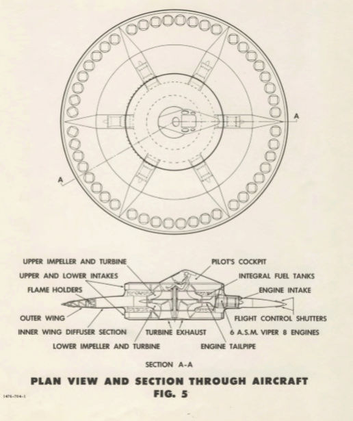

Again quoting from the Popular Mechanics article.
Getting off the ground is easy. Then it happens, as it always does: When the saucer rises above its 3-foot cushion of exhaust, it starts to buck like a rodeo bull. The researchers are crestfallen; they've seen this instability before. They call it hubcapping, after the circular way a car hubcap oscillates on its rim when dropped on hard ground. Potocki aborts the flight and sets the Avrocar down.
Over the years the engineers would test wide-ranging methods to control their craft: shaped nozzles, spoilers, skirts, bigger engine transition doors, vanes—even, at the suggestion of the Air Force, and to Frost's dismay, a tail. Nothing worked. The Avrocar never achieved stability in the air, and it never traveled faster than 30 knots or higher than 3 feet. So much for intercepting bombers.
Airman.Despite the impressive attempt, there’s not a whole lot here. Where’s the spin? This flying saucer is better described as a circular flying wing with a complex air intake and engine exhaust systems that apparently didn't work. I believe the “hubcapping” problem occurs because there’s no spin stabilization. I guess I just included the Project 1794 information for the Popular Mechanics article and pictures.
Any discussion?
.
LongtimeAirman- Admin
- Posts : 2023
Join date : 2014-08-10
Re: Flying Saucers?
![]() by LongtimeAirman Fri May 25, 2018 4:38 pm
by LongtimeAirman Fri May 25, 2018 4:38 pm
Back to the Mars Helicopter.
Airman. Well, yes. Here's an image from 48 seconds into the previous youtube video I posted Mars Helicopter https://youtu.be/oOMQOqKRWjU.Airman wrote. Alien Flying Propellers on Mars eh? Kinda sounds like the Drones in a vacuum experimental suggestion above - with vacuum at 1% earth standard atmosphere. I expect the drone will work, more on that later. Considering the stated 40,000ft helicopter altitude limit here on Earth vice the 100,000ft equivalent atmospheric pressure on Mars, why would they expect the drone to work at all? Wouldn't it be easier to perform the experiment at 1% standard air pressure or vacuum first? After all, they don't know that on its surface, Mars emits a stronger charge field than Earth does on its surface. It's such a tiny experiment. I must be missing something

We hear and see the rotors spinning, the copter on the floor, Quote “24 hundred, 26 hundred” and the copter lifts in the controlled experiment.
I also have additional information, from the Keck Institute for Space Studies http://kiss.caltech.edu/lectures/Aung_Lecture_2015.html, which links to the youtube file,
Mars Helicopter Scout [url=https://www.youtube.com/watch?v=w3y7iJEe7uM KISSCaltech]https://www.youtube.com/watch?v=w3y7iJEe7uM[/url]
Airman. Initial testing and analysis of the Mars Helicopter has been successfully completed – lift was generated by co-axial rotors under Mars-like conditions. The idea was shelved pending the decision earlier this month by NASA to include it in the 2020 rover mission.
KISSCaltech
Published on Nov 12, 2015
MiMi Aung, the Autonomous Systems Deputy Division Manager at JPL, presented the Mars Helicopter Scout at the Keck Institute for Space Studies lecture on April 1, 2015. The Mars Helicopter Scout is a current proposal to demonstrate helicopter flight at Mars on the Mars 2020 mission.The Mars Helicopter Scout will scout ahead of a planetary surface rover to provide high-resolution aerial images of the terrain for science and operational purposes. This talk described the scope of the Mars Helicopter Scout proposal, the signficant science and operational benefits of a helicopter in planetary surface exploration, and the technical design overview of Mars Helicopter Scout. … .

This image contains most of the Scout’s details. Both of the two-bladed counter-rotating propeller rotors are 1.1m in diameter. I don’t see a pitch adjustment mechanism. MiMi Aung mentioned that the max tangential spin velocity for rotors is the speed of sound – how does that work on Mars? I might suggest we could increase the charge lift created by replacing the currently planned rotor blades with ones where most of the rotor’s mass is closer to the highest spin velocity at the rotor’s outer edge.
The mainstream’s standard pressure fluid lift theory cannot explain how lift and thrust can be generated in the relative vacuum of Mars’ atmosphere - there’s not enough air for propellers to pull or push. Read the youtube comments, some people are very upset at NASA as well as with their own educations.
The charge field exists. Miles has proven that with at least a thousand examples. I think we can safely add the Mars Helicopter Scout to the list.
If I say something that you feel doesn’t agree with your charge field understanding, please jump in.
.
LongtimeAirman- Admin
- Posts : 2023
Join date : 2014-08-10
Re: Flying Saucers?
![]() by LongtimeAirman Mon May 28, 2018 12:52 pm
by LongtimeAirman Mon May 28, 2018 12:52 pm
No peeps; fair enough, I’ll need to make a better case for Coaxial Rotors.
Let me remind the reader, the goal here is to improve charge field awareness by choosing interesting “lift” subjects and seeing where the charge field takes us. I don’t have a lesson plan and I rarely read beyond the current idea being presented. I’m not trying to explain or entertain. I am trying to figure it out - in the open - in an effort to promote charge field physics with forum discussion. Until then, I’m dragging the reader through my stream of consciousness. Bear in mind, by the end of the thread I hope the reader may design her own flying saucer.
Coaxial Rotors. I found a great into to Coaxial Rotor Helicopters by Trevor English at http://shortsleeveandtieclub.com/ Trevor’s article includes the youtube video below as well as two nice gifs. I’ll quote his entire text, although I’ll interrupt it twice to add my charge field comments.
http://shortsleeveandtieclub.com/the-perfect-helicopter-understanding-coaxial-rotor-design/
How to Create the PERFECT Helicopter
https://youtu.be/a3IMqkffIFo
Published on Oct 10, 2017
The majority of helicopters are built using tail rotor systems, but this may not be the best design. Coaxial helicopters and the advantages they bring may be the future of helicopter engineering. Lockheed Martin along with Sikorsky have embarked on a journey to create a new breed of coaxial craft that could spell the future for multi-purpose helicopters. In this video, we take a look at not only this innovation, but just what makes coaxial craft potentially superior to other designs.
The Perfect Helicopter: Understanding Coaxial Rotor Design
April 4, 2017, by: Trevor English
Trevor English. Coaxial rotor designs have been used on military helicopters for the better part of the last 75 years. The design eliminates the need for a tail rotor and creates a much more stable, and safer, machine.
In order to understand how a design with two coaxial rotors far outperforms other helicopters, we have to examine the physics at play. For single-rotor helicopters, lift is generated through the main rotor rotating. This rotation generates torque about the main helicopter, which causes the main fuselage to want to spin around in the opposite direction. Early engineers designed the tail rotor to counter this torque and keep helicopters stable. Tail rotors are generally much smaller rotors mounted on a perpendicular axis to the main rotor. By controlling the speed of the tail rotor, the pilot can stabilize the craft as well as control direction of the helicopter.
Slowing the tail rotor would cause the helicopter body to rotate in the opposite direction of the main rotor due to excess torque in that direction. Speeding up the tail rotor would do the opposite. Along with direction, helicopter pilots can control the yaw of the craft by adjusting the angle of the tail rotor. By pitching the tail rotor slightly up or down, the pilot creates a moment arm through the helicopter which in turn adjusts the yaw of the craft.
Airman. Single - rotor helicopters generate torque on the body of the helicopter that must be countered by adding a tail rotor. Trevor didn’t explain why the torque is generated, in the video the narrator says that there is a net motion due to excess torque, that’s not an explanation.
The definition of charge lift easily explains why. Once again, as with the spinning disc, we must consider both the rotor’s forward and spin velocities, Vf and Vs, orthogonal to the earth’s emission field. A single rotor will feel maximum charge lift where Vf and Vs are in the same direction, while the least charge lift is created where Vf and Vs are in opposite directions.
A spinning disk that generates the same uneven charge lift is free to rotate its spin axis away from the vertical – recall understable, stable and overstable discs, defined in terms of how quickly they rotate away from their vertical spin axis in response to uneven charge lift. A spinning rotor is engine driven and of sufficient mass to prevent any axis rotation. The rotor behaves like a very stable gyroscope. The uneven charge lift felt by the rotor is equivalent to a tilting force applied to a gyroscope resulting in precession. The tail rotor’s primary purpose is to counter gyroscopic precession caused by uneven charge lift felt on the forward moving spinning rotor. The skilled pilot uses the tail rotor for additional control.
Trevor English. Now that we understand the basic mechanics of single-rotor helicopters, we can begin to see why coaxial rotors might present some advantages. By placing two rotors on a single axis and rotating them in opposite directions, a net zero torque around the main body of the helicopter is created, keeping it very stable. Through both mechanical means and electronic means, each rotor is perfectly timed and controlled to cancel out the net torque of the other rotor in real time. This allows coaxial craft to achieve rather significant hovering capabilities when compared to their single-rotor brethren.
Airman. I put together the following information that shows the magnitudes of the orthogonal velocities occurring for each rotor at the 0000, 0300, 0600, 0900, and center – 0 positions.
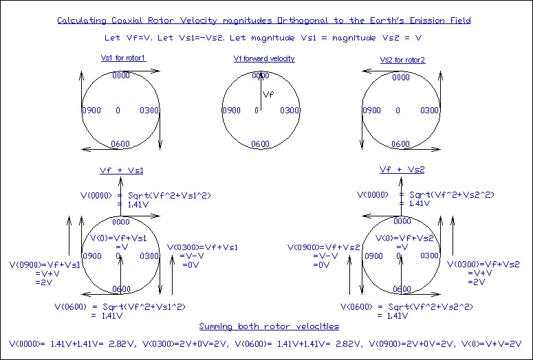
Calculating Coaxial Rotor Velocity Magnitudes. (As I did with the Frisbee flying disc, http://milesmathis.the-talk.net/t453p25-flying-saucers#3612). These velocities are orthogonal to the Earth's Emission Field, Charge lift is a function of these velocities.
When viewed from above, the Forward velocity Vf, is vertically upward on the page. The rotors are: S1 spinning clockwise (CW) at tangential spin velocity Vs1; and S2 is spinning CCW at the tangential spin velocity Vs2. Let: Vs1 = -Vs2; magnitude V = |V|; |Vs1| = |Vs2| = V; |Vf | = V. The magnitude of the orthogonal velocity Vo, is then calculated for 5 positions for each rotor.
0000 (or 1200) position:
S1. Vo = sqrt[Vf^2 + Vs1^2] = sqrt[2* V^2] = 1.41V.
S2. Vo = sqrt[Vf^2 + Vs2^2] = sqrt[2* V^2] = 1.41V.
Vt = 1.41+ 1.41V = 2.82V.
0300 position:
S1. Vo = Vf + Vs1 = V - V = 0V.
S2. Vo = Vf + Vs2 = V + V = 2V.
Vt = 0V + 2V = 2V.
0600 position:
S1. Vo = sqrt[Vf^2 + Vs1^2] = sqrt[2* V^2] = 1.41V.
S2. Vo = sqrt[Vf^2 + Vs2^2] = sqrt[2* V^2] = 1.41V.
Vt = 1.41+ 1.41V = 2.82V.
0900 position:
S1. Vo = Vf + Vs1 = V + V = 2V.
S2. Vo = Vf + Vs2 = V - V = 0V.
Vt = 0 + 2V = 2V.
Center position:
S1. Vo = Vf + Vs1 = V + 0 = V.
S2. Vo = Vf + Vs2 = V + 0 = V.
Vt = V + V = 2V.
I believe each of the two rotors contributes lift and so the two rotor velocities must add. Both velocity sets are directly added for the total coaxial rotor velocities. Anyone agree or disagree?
1200: Vt = 1.41+ 1.41V = 2.82V
0300: Vt = 0V + 2V = 2V.
0600: Vt = 1.41+ 1.41V = 2.82V
0900: Vt = 2V + 0V = 2V.
Center: Vt = V + V = 2V.
The total velocities at each of the three positions: 0300, Center, and 0900 add to 2V. The front and back spin edges of the coaxial rotors are moving fastest with respect to earth’s emission at 2.82V, resulting in two maximum charge lift points. Since those two positions are on opposite sides of the rotor, the two tilting forces applied will cancel and so gyroscopic precession will not occur. Likewise, the maximum velocity – 2V - of each individual rotor also causes two simultaneous tilting forces at 0300 and 0900 which also cancel.
Trevor English. When you think of helicopters, you think of vertical takeoff and the ability to hover. Remove those aspects, and the helicopter functions identically to a plane. As a side note, vertical takeoff isn’t exclusive to rotor craft, however planes that harness the ability without rotors – mainly the harrier jet – accomplish the task with much less efficiency and stability.
A helicopter’s ability to hover and be stable is synonymous with its quality of being a helicopter. In coaxial designs, the improved ability to hover and maintain stable flight ultimately make for better helicopters. Better helicopters mean that they are easier to control and much safer for the occupants. Theoretically, if one rotor broke in a coaxial system, the craft could still be landed safely.
Lastly, the application of coaxial rotors means that there is no inherent need for the craft to have a gyroscope to provide stability. The rotational effects of both rotors provide for a near perfect gyroscope, improving the stability of the craft once more.
So why don’t we see more coaxial helicopters? They aren’t without their faults.
The first main fault is that the timing of the two rotor blades needs to be near perfect. Speed and directional changes need to be accomplished together. Even the slightest fault in calibration essentially makes the aircraft unstable and unflyable. A fault in calibration is worse than you probably think for the craft’s ability to fly. If the timing is off enough, coaxial helicopters won’t produce enough lift to even leave the ground and end up just spinning on the tarmac.
On top of the need for accuracy in the tuning of the rotors, these rotors tend not to be as responsive as single rotor craft. When you make an aircraft more stable, you generally make precise movements harder to achieve – it’s a constant tradeoff in aerospace engineering. While coaxial helicopters are safe and efficient, they are not well suited for applications where pilots need fine maneuverability. They are, however, perfect for applications where precise hovering is needed.
The coaxial rotor design is one of the most prominent helicopter designs to date. While it has it’s inefficiencies, it won’t be going away anytime soon. The stability of the design is popular within the hobbyist community and even many military and rescue helicopters to date. If you were designing a helicopter, which design would you choose?
Airman. All good information. Let me rephrase that. If you were designing a flying saucer, which design would you choose?
P.S. Some small corrections: 3 procession to precession, a few number corrections and added the sentence beginning with Likewise.
P.P.S. Trevor English wrote. The first main fault is that the timing of the two rotor blades needs to be near perfect. Speed and directional changes need to be accomplished together.
Airman. If you hadn’t already noticed, I must point out that the 0000, 0300, 0600, 0900, positions are important; that’s where the rotor’s maximum and minimum orthogonal velocities are created, where tilt and counter-tilt must occur. If Vs1 = -Vs2, the two twin-bladed counter-rotating rotors must align twice during each full rotor rotation. “Perfect timing” can only be achieved when each rotor extends to both: 0000/0600; or 0300/0900 – simultaneously; call it spin rate and angle synchronization.
Of course, the coaxial helicopter isn’t being lifted by just the 0000, 0300, 0600, 0900, and center positions alone. All the atoms of which the rotors are comprised are lifted to varying degrees, corresponding to the amount of planetary emissions they receive. Most emissions intercepted, or charge lift generated, lies closest to the highest velocity rotor edge.
I’ll also point out that I’ve concentrated on constant velocity, things get more complicated with speed and direction changes.
.
Last edited by LongtimeAirman on Wed May 30, 2018 7:14 pm; edited 2 times in total (Reason for editing : Added PPS)
LongtimeAirman- Admin
- Posts : 2023
Join date : 2014-08-10
Re: Flying Saucers?
![]() by Cr6 Wed May 30, 2018 1:04 am
by Cr6 Wed May 30, 2018 1:04 am
Found these that may be of interest:
https://diydrones.com/profiles/blogs/researchers-say-triquad-is-more-efficient-than-a-quad

http://www.krossblade.com/disc-loading-and-hover-efficiency/
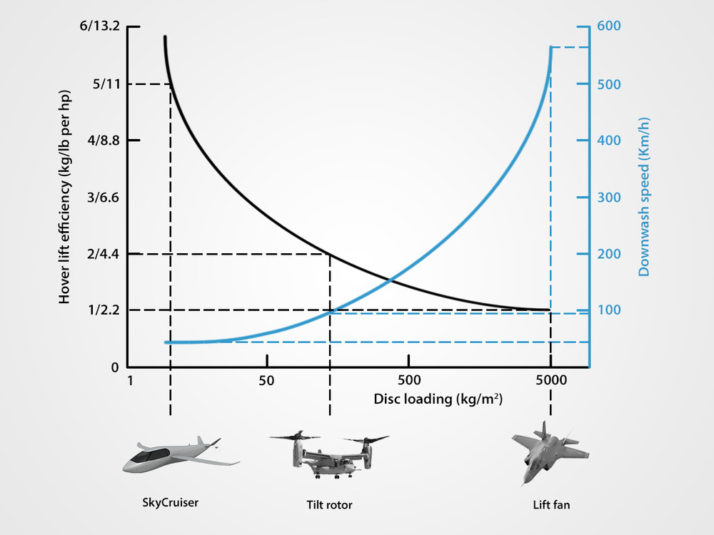

An extreme example of this is the AeroVelo Atlas shown left, a human powered quadrotor. Due to ultra-light weight construction it only weighs 128 kg (282 lb) with pilot (which can produce about 1 hp), but it has a massive disc area of almost 1,300 sqm (14,000 sqf). This is more than twice the disc area of the largest helicopter in the US military, the Sikorsky CH53 E Super Stallion, which with a maximum weight of 33,000 kg (74,000 lb) is almost 300 times more heavy than the AeroVelo Atlas. The Atlas' super low disc loading of 0.1 kg/sqm translates into a hover efficiency of 128 kg/hp. CH 53E on the other hand, with its disc loading of around 70 kg/sqm (700 times more heavily loaded than the ATLAS), requires around 10,000 hp to take off which translates into a hover efficiency of only 3.3 kg/hp. The Atlas hence has a hover efficiency around 40 times better than the Super Stallion. An even more extreme example is the F 35 Lightning. It's thrust vectoring and lift fan VTOL system has a disc area of only around 6 sqm (60 sqf) for a weight of up to 30,000 kg (66,000 lb), giving it a disc lading of around 5,000 kg/sqm, around 50,000 times more heavily loaded than the ATLAS. Consequently the F35 requires around 30,000 hp to take off, meaning that it's hover efficiency is only 1 kg/hp, 128 times less efficient than the ATLAS.
Hover efficiency versus disc loading. Lower disc loading is more efficient, meaning less power is required to hover. (Krossblade) Hover efficiency versus disc loading. Lower disc loading is more efficient, meaning less power is required to hover. (Krossblade)
Hover efficiency versus disc loading. Lower disc loading is more efficient, meaning less power is required to hover. (Krossblade)
The general relationship between disc loading and hover efficiency is shown in the graph on the right. What a rotor basically does is to push air downwards in order to push itself upwards (Newton's third law). Broadly speaking, producing the same upwards force, it is more energy efficient to do this moving a larger volume of air downwards more slowly, than moving a smaller volume of air downwards more quickly. This also means that not only does a higher disc loading lead to lower efficiency, it also leads to more severe down wash (the air that for example a helicopter blows downwards and into the faces of onlookers) and also to larger noise from the faster moving blades and air.
So why not make helicopters with huge disc areas, thousands of square meters (tens of thousands of sqf) in order to lift off with very little power? There are several reasons:
1) Large blades make the helicopter more sensitive to wind gusts, the heli becomes less stable
2) Very large and very slowly moving blades would limit the possible forward speed to only a few kph or mph
3) Space considerations also guide helicopter design, a heli has to be able to land in small spaces and park
4) Large blades are technically more challenging to build and can get very heavy
Cr6- Admin
- Posts : 1178
Join date : 2014-08-09 -
Re: Flying Saucers?
![]() by LongtimeAirman Wed May 30, 2018 7:26 pm
by LongtimeAirman Wed May 30, 2018 7:26 pm
Cr6 wrote. Nice research LTAM. How to develop a craft to tap the charge field at different heights/gravity? Could a craft be built that could adapt dynamically...just to get a little extra lift?
Airman. Hi Cr6, thanks for helping me collect my wits. I added a PPS to my previous post. What research? There’s too much information so I’m trying to cut back.
I’ll admit I’m happy I included the spin component, Vs, in accordance with Miles’ definition of charge lift. Lift is a function of the object’s velocity orthogonal to Earth emission field, so that, Vo = Vf +Vs. Of course, my ‘charge lift’ diagram doesn’t exactly agree with existing lift diagrams; take this mainstream single-rotor for example.
Dissymmetry of Lift
http://www.copters.com/aero/lift_dissymetry.html

QUOTE. Dissymmetry of lift is the difference in lift that exists between the advancing half of the rotor disk and the retreating half. It is caused by the fact that in directional flight the aircraft relative wind is added to the rotational relative wind on the advancing blade, and subtracted on the retreating blade. The blade passing the tail and advancing around the right side of the helicopter has an increasing airspeed which reaches maximum at the 34 o'clock position. As the blade continues, the airspeed reduces to essentially rotational airspeed over the nose of the helicopter. Leaving the nose, the blade airspeed progressively decreases and reaches minimum airspeed at the 9 o'clock position. The blade airspeed then increases progressively and again reaches rotational airspeed as it passes over the tail. UNQUOTE.
Airman. Looking down on a counter clockwise spinning rotor advancing in the forward (upward in the page image) direction. According to the mainstream, lift is created at the “advancing” or “leading”, along the rotor blades’ length, resulting in a maximum lift created at the 0300 rotor direction. This mainstream differential airspeed lift model does not account or allow for lift created when rotors are extended in the 0000/0600 directions. I’ve shown that the charge lift model does.
Most aircraft are built for efficiency; given strict power, performance and weight limits - dynamic costs extra. The SkyCruiser, on the bottom left of the efficiency/power chart you posted is a good example. It utilizes quad rotors for lift, then the craft switches to rear rotors for horizontal thrust – airplane mode, during which the quad rotors are retracted into the fuselage, very smooth. On the right side of the chart we have a fighter jet with thrust vectoring for vertical take-offs or landings, as well as high speed horizontal thrust; it’s dynamic – and wildly expensive.
Given the charge field, can we design craft with a little extra lift? I believe so. I’ll share more on that later. I’m still considering possibilities that I cannot believe have not already been tried. In general, it seems helicopters - quads and coaxials - are enjoying a bit of revival, probably because of drones. Here’s a nice aviation discussion from stackexchange.
Why haven't quadcopters been scaled up yet?
https://aviation.stackexchange.com/questions/3300/why-havent-quadcopters-been-scaled-up-yet
Airman. This 1931 helicopter looks to me to be a coaxial dual quad, and it also appears to have a small forward 4 bladed rotor.QUOTE. Four rotor copters were actually the first copters...
Raúl Pateras Pescara, Buenos Aires, Argentina, 1916
UNQUOTE.

Given the stackexchange question, the top answer belongs to Jan H. I’ll quote one paragraph.
Jan wrote. And why can't full-scale helicopters use electric motors like the small ones? The reason is that when you scale an airfoil up, the lift it produces increases with its area, which grows with the second power of size, but its weight increases with volume, which grows with the third power of size. Therefore models have much more lift for weight and can afford simple but relatively heavy batteries while full-size aircraft need propulsion systems with higher power density.
Airman. I believe that answer is consistent with the mainstream assumption that air is a fluid. We know that is incorrect in that it ignores the charge field.
As I’ve constantly been reminding the reader, every atom within the volume of the airfoil will feel charge lift according to its orthogonal velocity through the emission field. Yes, charge lifted air and propeller thrust add complexity; still, charge lift applies to the entire volume and not just surface area.
Granted, there’s a huge performance difference between aircraft and small models. There’s also a perfectly good charge field explanation. Recall that humans occupy the meter scale, where gravity and charge balance. Objects smaller than a meter are in the charge realm, while larger objects interact mainly with gravity. I’m sure this answer is essentially correct, but I’m not sure what it means. For example, here’s a question I haven’t been able to answer.
QUESTION. Earth charge emission counters 0.1% of gravity for an adult human. Would a house fly also enjoy the same 0.1% gravity reduction? If so, what’s the difference?
.
Last edited by LongtimeAirman on Fri Jun 01, 2018 10:00 pm; edited 1 time in total (Reason for editing : Two typos)
LongtimeAirman- Admin
- Posts : 2023
Join date : 2014-08-10
Re: Flying Saucers?
![]() by LongtimeAirman Fri Jun 01, 2018 9:54 pm
by LongtimeAirman Fri Jun 01, 2018 9:54 pm
Cr6 wrote. Could a craft be built that could adapt dynamically...just to get a little extra lift?
Airman. Yes, but having given it some thought, I don’t believe “a little extra lift” means what you think it means. For example, let’s take a ride on a thought train – something fast and smooth – a hovertrain will do; and bring a weight scale.
The Problem With Fast Trains: What Happened to Hovertrains?
https://www.youtube.com/watch?v=qUXEFj0t7Ek
Ok, with the train and us in motion, at any velocity orthogonal to the earth’s emission field, we must be receiving increased charge lift. The train can “adapt dynamically” by increasing speed. Our weight - gravity minus charge lift - should reduce. Please stand on the scale and check. Normal, right? How can that be true? Does that invalidate the charge lift model?
My guess is the entire train, as well as us, the scale you are standing on and the air in the cabin are being charge lifted to the same degree and so – at least as far as I imagine - the scale doesn’t measure any decrease in weight. However, if we replace the scale with a different measuring device, such as pendulums – as in Miles’ Allais paper – I believe we should see an increased charge lift and reduction of weight aboard the moving train as an increase in a pendulum’s fundamental period - the time it takes for the pendulum to complete a single back and forth swing.
The same thinking pertains my house fly question. Yes, I suppose the fly feels the “same” 0.1% gravity reduction, and on the train it would receive the same increased charge lift we would. In either case, the fly’s small mass and physical dimensions – much smaller than a meter - along with its amazing velocity and acceleration capabilities allow the fly to exceed the acceleration due to gravity on Earth (9.8m/s^2). Objects larger than a meter generally have slower velocities and take a greater amount of time or energy to accelerate to higher speeds, as in the human powered quad copter posted above – built as light as possible.
Moving at higher and higher velocity orthogonal to the earth’s surface results in increasing charge lift. If, by “a little extra lift”, you meant negative buoyancy or weightlessness, then I guess the craft must be able to reach orbital velocity - actually an acceleration - curved motion about the planet, at which time we would float inside our craft. I would then give you a battery powered hand held propeller someone might use to cool themselves off in hot weather, it will allow you to easily propel yourself through the craft’s weightless conditions.
Agree, disagree?
.
LongtimeAirman- Admin
- Posts : 2023
Join date : 2014-08-10
Re: Flying Saucers?
![]() by LongtimeAirman Mon Jun 04, 2018 11:19 pm
by LongtimeAirman Mon Jun 04, 2018 11:19 pm
Somehow, the train has remained on track, while moving at hundreds of times faster than sound – along the earth’s surface, and orthogonal to the earth’s emissions. You may recall Cr6 and I had achieved weightlessness and so I gave Cr6 a tiny propeller for “a little extra lift”. I was hoping to avoid the inevitable childlike behavior - bouncing and careening in all directions -
A train usually travels at a maximum forward velocity in a straight path on the Earth’s surface. Of course, the Earth isn’t flat; at orbital velocity, motion along a well-designed track of the future requires that the track keep the train on the earth’s surface; I like the idea of underground partial vacuum tubes to minimize air resistance. During weightlessness, the track must impose a downward velocity equal in magnitude to the train’s very high forward velocity. For the calculation I’m thinking the orbital velocity should be equal to Earth’s radius divided by 18 minutes (earth radius doubling period), which gives me a forward velocity of about 106km/sec – but I’m not at all confident with that result.
Before we reach orbital velocity, we could probably experience any weight we wanted - as long as it is less than g - by selecting the appropriate forward velocity; again, the track will impose the corresponding downward velocity. Those two orthogonal velocities together create the acceleration necessary in order to achieve the desired weight.
Curved motion about a circular track around the earth.
Any mistakes, questions or comments?
////////////////////////////////////////////////////
No surprise, I’ve been considering flying saucer design requirements a lot lately. After watching a fast train video on youtube, I tried a suggested link - Reactionless UFO Propulsion #2. A minute and a half section, early in the video sounded good enough to share here. The narrator’s tone and cello accompaniment made listening meditative; you may appreciate my transcription instead. Oh, I never tried the cc button before; hah, my transcript’s better. Something new every day.
Reactionless UFO Propulsion #2
https://www.youtube.com/watch?v=0aSX9TakHnc
Bantokfomoki. Published on May 7, 2010. 9 min:59 sec in length.
From: 0:34 to 2:06 the Narrator states:
The image shows one of the "extremely limited" ways we may possibly shift a vector out of the plane of rotation – using intense magnetic fields. Getting required vectors “out of the plane of rotation” via “reactionless propulsion” sounds new to me. Is there anything to it? On the spin side, I’ve learned a bit more about spinning and forward motion so I would add -QUOTE: My proposal is that something rotates in the UFO and the centrifugal vectors are made to be non-coplanar with the rotation.
If one could point these centrifugal vectors out of the plane of rotation, accelerations of a hundred g’s and more are easily realizable and the conservation laws are no are longer an impediment because you are then violating them with impunity.
One of the aspects of such a system of propulsion is that the weight of the rotating part should be as heavy as possible because it needs to propel the deadweight of the rest of the craft.
And trace cases of UFO landings indicate that their mass density correspond more to submarine densities than to a jet fighter or aircraft.
I expect the craft itself to be made of the lightest strongest materials and the propulsion system’s rotational part to be as heavy as possible.
To get the required vectors out of the plane of rotation requires some action to get them to shift.
The things that one can do to accomplish this are extremely limited.
We can subject the wheel to intense magnetic or electric fields, and perhaps heat it or cool it to superconducting temperatures.
That’s all there is in this universe to operate on the wheel. If the forgoing doesn’t do the trick nothing else will. For we are then left with just wishing and clicking our heels together. … UNQUOTE.

The rotational system should include contra-rotating rotors or masses.
It looks to me like I may need to reconsider Otis T Carr’s X-1 again.
.
LongtimeAirman- Admin
- Posts : 2023
Join date : 2014-08-10
Re: Flying Saucers?
![]() by Cr6 Sun Jun 10, 2018 2:32 am
by Cr6 Sun Jun 10, 2018 2:32 am
Cr6- Admin
- Posts : 1178
Join date : 2014-08-09 -
Re: Flying Saucers?
![]() by LongtimeAirman Sun Jun 10, 2018 11:36 pm
by LongtimeAirman Sun Jun 10, 2018 11:36 pm
Thanks Cr6,
Charge lift.
Lift - or charge lift – pertains to the amount of charge emission a body feels in opposition to gravity. Here on Earth’s surface, lying, standing or siting, we would weigh 0.1% more were it not for the Earth’s vertical emission field bombarding all of our atomic matter upward. I suppose I agree, 0.1% seems like a small amount of lift – a thousandth of our weight - can we generate more? Yes.
The first and easiest way to feel “extra lift” is by forward motion – velocity orthogonal to the earth’s emission field. Walking creates extra lift. We feel a great deal of extra lift when we run or sprint. Additional lift is felt at higher velocities. This lift is felt equally throughout the object in motion.
The next way to add “extra lift” is by adding spin motion (with spin axis parallel the earth’s emission field). This lift is felt as a function of distance from the center of rotation. Rotation creates a new outward emission field. I believe Miles addressed the additional lift felt by rotation as upward charge that is redirected outward – turning charge. With the Lifter, we saw that turning charge alone - at tens of thousands of volts - was sufficient to keep the lifter suspended in the air. It’s not at all clear to me how forward linear motion turns charge.
I believe we can create additional lift by increasing either mass volume or mass density; it will take additional energy to move those additional masses, but the efficiency gained may justify the effort.
Cr6 wrote. Could the extra lift come from a graphene blade that could adapt programmatically "on-the-fly" so to speak. For some reason the lift from old copper plated wings comes to mind.
Propellers.
The first complication is an air or fluid medium which is also charge lifted – I assume at 0.1%. Moving air or water causes extra lift and flows. Ancient technology - spinning propellers – have been shown to generate thrust – motion in the direction of the propeller spin axis - that can far exceed the charge lift or charge turning I’ve been describing.
Can spinning propellers be used to cause thrust in a vacuum? I don't know, but I believe so, the vacuum must act like a very thin fluid. Proof is the Mars Scout Helo with counter-rotating, 1.1m diameter rotors spinning at 2400 rpm. The prototype was shown to generate lift in Martian simulated 1% Earth atmosphere. How can that be? We know about the charge field; they, presumably, do not.
So how do propellers work in vacuum? Can varying such propeller blade pitches affect the resultant direction of thrust? I'll keep thinking about it.
Flying Saucers? My first Flying Saucer design is comparable to an alpha, a helium atom. Two counter rotating coaxial rotor masses resemble the two opposite polarity alpha proton emission fields. Living quarters would be aboard the "neutrons" spinning at a much slower velocity - in order to generate gravity - between the two counter-rotating rotor masses. Modeling a spacecraft after an atom or molecule makes a great deal of sense in providing additional charge protection when rotating masses intercept and channel increased charge densities outward.
.
LongtimeAirman- Admin
- Posts : 2023
Join date : 2014-08-10
Re: Flying Saucers?
![]() by LongtimeAirman Wed Jun 13, 2018 12:34 am
by LongtimeAirman Wed Jun 13, 2018 12:34 am

Demonstrating some progress - mostly with Autocad. The program will not allow each section its own rotation, but you get the idea.

.
LongtimeAirman- Admin
- Posts : 2023
Join date : 2014-08-10
Chromium6 likes this post
Re: Flying Saucers?
![]() by LongtimeAirman Wed Jun 13, 2018 4:46 pm
by LongtimeAirman Wed Jun 13, 2018 4:46 pm
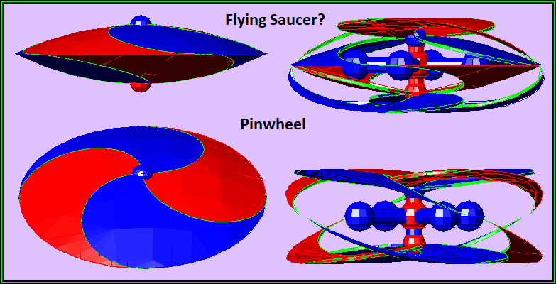
And I believe a slightly better second effort. A saucer that opens up into a sort of pinwheel. Again, if the bottom rotors are going to the right - as shown below, then the top propeller rotors should be rotating to the left - they are not; as far as I know, my Autocad doesn't allow it. The four neutrons can spin in a single direction independently of the top or bottom rotors.
The closed - and counter-rotating saucer may provide all the lift necessary in space; however, in Earth atmosphere, I believe the saucer would need to open up into a pinwheel in order to generate thrust.
.
LongtimeAirman- Admin
- Posts : 2023
Join date : 2014-08-10
Chromium6 likes this post
Re: Flying Saucers?
![]() by Cr6 Thu Jun 14, 2018 12:39 am
by Cr6 Thu Jun 14, 2018 12:39 am
Found something that may be of interest. How to stop a missle?
--------
"It Looks Like An Ascending Missile," Unidentified Object Photographed Over Washington State, Navy Denies
by Tyler Durden
Wed, 06/13/2018 - 11:45
It’s time to get out that tinfoil hat.
Greg Johnson of Skunk Bay Weather, a local weather website that runs camera enabled weather stations on the northern Kitsap Peninsula; Kitsap County, Washington, recorded a mysterious object early Sunday morning that has social media buzzing.
One of Johnson’s weather stations has a camera monitoring the Puget Sound at Whidbey Island from Skunk Bay, and at 3:56 a.m. Sunday by a high-resolution, 20-second exposure camera, snapped what looks like the impossible — a missile blasting off from what seems to be the Naval Air Station Whidbey Island.
My good night cam picked up what appears to be a large missile launch on Whidbey Island Sunday AM. I sat on it for a while. After sharing with Cliff Mass he did a blog on it. https://t.co/jBPXRtRGFP @NWSSeattle @WunderCave @WeatherNation pic.twitter.com/RnN8H3IsQ9
— Skunkbayweather (@Skunkbayweather) June 11, 2018
Johnson told KCPQ13 Washington, he was at first hesitant to release the photo into the public domain because he said it appears to be a missile launch from the Naval Air Station Whidbey Island across the bay.
“I feel strongly it was a missile launch,” Johnson said.
But Tom Mills, a spokesperson for NAS Whidbey Island, told KCPQ13 that “It wasn’t a missile launch from the facility. There are no missile launch capabilities on the Navy base at Whidbey Island.”
“There’s a lot of speculation around here,” Mills said, as he conveniently suggested to KCPQ13 that the image could be a lens flare. “But it’s definitely not a missile launch.”
Cliff Mass, a professor of Atmospheric Sciences at the University of Washington, speculated that the object looks like a missile on his blog Monday.
“I’ve seen a lot of stuff,” Mass wrote. “But nothing like this.”
“It really looks like an ascending missile,” he added.
There was reportedly Alaska Flight 94 and a helicopter in the region of the northern Kitsap Peninsula at the same time the camera snapped the mysterious object.
In responding to speculation of various aircraft overhead, Johnson said, “For the record… My cams pick up airplanes all the time… I can guarantee this is NOT an airplane. They fly buy much higher and have a whole different signature….. I’ll grab a plane image and share it.”
For the record... My cams pick up airplanes all the time... I can guarantee this is NOT an airplane. They fly buy much higher and have a whole different signature..... I'll grab a plane image and share it.
— Skunkbayweather (@Skunkbayweather) June 11, 2018
Furthermore, The Drive points out that there are no rocket operations of any kind in the region. However, the “closest thing to something like that would be the Ohio class nuclear ballistic missile submarines (SSBNs) based not too far away at Bangor Trident Base/Naval Submarine Base Bangor.”
http://skunkbayweather.com/

Cr6- Admin
- Posts : 1178
Join date : 2014-08-09 -
Re: Flying Saucers?
![]() by LongtimeAirman Fri May 08, 2020 9:49 pm
by LongtimeAirman Fri May 08, 2020 9:49 pm
A possible new technology for jet engines?
Scientists Create a Prototype 'Air Plasma' Engine That Works Without Fossil Fuels
https://www.sciencealert.com/scientists-have-created-a-fossil-fuel-free-jet-engine-prototype
DAN ROBITZSKI, FUTURISM
6 MAY 2020
The device compresses air and ionizes it with microwaves, generating plasma that thrusts it forward, according to research published Tuesday in the journal AIP Advances. That means planes may someday fly using just electricity and the air around them as fuel.

/////\\\\\/////\\\\\/////\\\\\
And the source paper that article links to.
Jet propulsion by microwave air plasma in the atmosphere
https://aip.scitation.org/doi/full/10.1063/5.0005814
.ABSTRACT We propose a prototype design of a propulsion thruster that utilizes air plasma induced by microwave ionization. Such a jet engine simply uses only air and electricity to produce high temperature and pressurized plasma for jet propulsion. We used a home-made device to measure the lifting force and jet pressure at various settings of microwave power and the air flow rate. We demonstrated that, given the same power consumption, its propulsion pressure is comparable to that of conventional airplane jet engines using fossil fuels. Therefore, such a carbonemission free thruster could potentially be used as a jet thruster in the atmosphere.2020 Author(s). All article content, except where otherwise noted, is licensed under a Creative Commons Attribution (CC BY) license (http://creativecommons.org/licenses/by/4.0/). https://doi.org/10.1063/5.0005814
LongtimeAirman- Admin
- Posts : 2023
Join date : 2014-08-10
Chromium6 likes this post
Re: Flying Saucers?
![]() by LongtimeAirman Sat Sep 26, 2020 7:38 pm
by LongtimeAirman Sat Sep 26, 2020 7:38 pm
How Tic Tacs work.
Back in April 2020 the Telegraph reported that the Pentagon released three ufo videos. https://www.telegraph.co.uk/
Pentagon releases 'UFO' videos filmed by US Navy pilots
850,869 views•Apr 27, 2020
The Pentagon has released three declassified videos showing US Navy pilots encountering what appear to be unidentified flying objects (UFOs) “to clear up any misconceptions”.
////\\\\////\\\\////\\\\////\\\\
One of the three videos shows a ufo referred to as a Tic Tac. The Tic Tac can change its speed and direction instantaneously.
David Fravor, a Navy pilot who ‘chased’ a Tic Tac describes his experience in an interview conducted by Lex Fridman.
The Tic Tac UFO Story | David Fravor and Lex Fridman
Sep 11, 2020
\\\\////\\\\////\\\\////\\\\////
A theoretical physicist, Dr. Jack Sarfatti claims he knows how the Tic Tacs fly.
Dr. Jack Sarfatti: I Know How Tic Tacs Work, the US Does Not.
9 Mar 2020.
Sarfatti is a theoretical physicist and a world-renowned expert in quantum physics. He co-wrote the book Space-Time and Beyond. He claims to have scientific formulas making the production of these craft possible. He is certain, however, that what was seen by Navy personnel is not U.S. craft. He has a very unusual theory as to what they are.
Airman. I’d prefer to stick to Dr. Sarfatti’s physical explanation, but a brief larger view is necessary. Dr. Sarfatti wants ten minutes of the president’s tme to convince him to fund billions for his ideas. Dr. Sarfatti tells us is from Flatbush, Brooklyn New York. He describes being part of a large group of teenagers coddled and supported by the government, it seems he was enlisted by the CIA in the 70’s to aid in paranormal studies, among other things. His teachers were the engineers who built the early fission bombs. He knows all the experts. Dr. Sarfatti is certain that an autonomous Tic Tac supercomputer from the future contacted him as a young teen to learn the knowledge of Tic Tacs.
The physics. According to Dr. Sarfatti, what all the experts get wrong is the fact that gravitation is not a force, it’s a field. Refraction is proof that the speed of light is different in different materials. The gravitational field can be described by 8PiGn^4/c^4. Where G is the gravitational constant, c is the speed of light and n is the index of refraction. The Tic Toc is made of a meta material that forms its own gravity field when we apply the materials’ resonant frequency. By proper application of power, one can control the speed of light passing through the meta material, which also controls the Tic Tac motion through space.
I hope that’s all correct.
I do not believe that Dr. Sarfatti‘s ideas agree in any way with my understanding of the charge field. I'll stick to one item, refraction. Refraction is not proof that light travels at different speeds through different materials. The speed of light through much larger molecular structures - not necessarily including charge recycling - is always c. In The Laws of Refraction, * Miles explains that refraction is caused by a material’s emission field, dense with photons recycled through resonant molecules.
Miles wrote. It doesn't matter how thin it is, if it is made up of different elements, it is going to have a different charge field. All the baryons and electrons in that layer are recycling charge photons, so the charge field in that layer will have its own particular spin and direction. In this way, we see that it is not photons being absorbed by gold or silicon that causes the refraction, nor is it photons being trapped by nano-resonators. It is photons being physically deflected by other photons already present in the charge field. And since the charge field is better equipped to deflect than the matter field, our question is answered. I remind you that the classical E/M equations (by classical I mean Maxwell, here) have always contained the following important information: the charge field outweighs the matter field by 19 times. And that applies in normal situations, not just esoteric or “dark matter” situations.
P.S. I suppose I should provide some charge field based explanation for why Tic Tacs fly. My guess involves spinning, such as an internally spinning gyroscope flywheel. A rapidly spinning mass will interact, or deflect, more upward directed earth emissions, thereby reducing gravity.
Dr. Sarfatti suggested that the Tic Tac’s surface contains nano structures like Russian nested dolls. I could imaging that spinning nested molecules might interact with the earth’s emission field in the same way.
*
http://milesmathis.com/index.html
.310a. The Laws of Refraction. http://milesmathis.com/rain3.pdf A refutation of the new SEAS experiment. 4pp.
LongtimeAirman- Admin
- Posts : 2023
Join date : 2014-08-10
Chromium6 likes this post
Re: Flying Saucers?
![]() by Chromium6 Mon Sep 28, 2020 8:42 pm
by Chromium6 Mon Sep 28, 2020 8:42 pm
Chromium6- Posts : 723
Join date : 2019-11-29
Re: Flying Saucers?
![]() by LongtimeAirman Fri Oct 09, 2020 1:12 pm
by LongtimeAirman Fri Oct 09, 2020 1:12 pm
Yep Cr6, I always liked this thread, and Tic Tacs are interesting. It would be nice to figure out, or reverse engineer in strict accordance with the charge field, how they might fly either underwater, through air or space. Unfortunately, there are many clearly charge field impossible claims such as, ‘tic tacs travel faster than light’, or latest popular buzz concepts like 'torsion fields'. For example.
Planetary Corporations, Tic Tac UFO's, Pentagon's UFO Unit
Airman. In Planetary Corporations, ... , Yes, Tic Tacs can fly faster than the light speed, using highly classified anti-gravity, torsion field type warp drive and engines. Tic Tacs belong to Planetary Corporation – the highest echelon of the U.S. Air Force. Planetary Corporation has been on the Moon since the 50’s and Mars since the 80’s. Tic Tacs are built in Mars orbit. Russia and China have their own space forces.
I apologize, that that’s too over-the-top; although, between you and me, I assume humans have been around long enough to have established off-earth economies. Not to mention non-human sentient beings. ... . Who knows?
Here’s probably a better source containing plenty of additional information.
https://ufos-scientificresearch.blogspot.com
An examination of aspects of Unidentified Aerial Phenomena (UAP) from a scientific perspective.
https://ufos-scientificresearch.blogspot.com/search?q=tic+tac
I did a site search on ‘tic tacs’ and see 7 articles to choose from. If I wasn't such a political junkie caught up in current events, I would have read them by now.
.
LongtimeAirman- Admin
- Posts : 2023
Join date : 2014-08-10
Chromium6 likes this post
Re: Flying Saucers?
![]() by Chromium6 Sun Oct 11, 2020 3:53 pm
by Chromium6 Sun Oct 11, 2020 3:53 pm
------
The force is strong in neutron stars
Study identifies a transition in the strong nuclear force that illuminates the structure of a neutron star’s core.
Jennifer Chu | MIT News Office
Publication Date:February 26, 2020
Most ordinary matter is held together by an invisible subatomic glue known as the strong nuclear force — one of the four fundamental forces in nature, along with gravity, electromagnetism, and the weak force. The strong nuclear force is responsible for the push and pull between protons and neutrons in an atom’s nucleus, which keeps an atom from collapsing in on itself.
In atomic nuclei, most protons and neutrons are far enough apart that physicists can accurately predict their interactions. However, these predictions are challenged when the subatomic particles are so close as to be practically on top of each other.
While such ultrashort-distance interactions are rare in most matter on Earth, they define the cores of neutron stars and other extremely dense astrophysical objects. Since scientists first began exploring nuclear physics, they have struggled to explain how the strong nuclear force plays out at such ultrashort distances.
Now physicists at MIT and elsewhere have for the first time characterized the strong nuclear force, and the interactions between protons and neutrons, at extremely short distances.
They performed an extensive data analysis on previous particle accelerator experiments, and found that as the distance between protons and neutrons becomes shorter, a surprising transition occurs in their interactions. Where at large distances, the strong nuclear force acts primarily to attract a proton to a neutron, at very short distances, the force becomes essentially indiscriminate: Interactions can occur not just to attract a proton to a neutron, but also to repel, or push apart pairs of neutrons.
“This is the first very detailed look at what happens to the strong nuclear force at very short distances,” says Or Hen, assistant professor of physicst at MIT. “This has huge implications, primarily for neutron stars and also for the understanding of nuclear systems as a whole.”
Hen and his colleagues have published their results today in the journal Nature. His co-authors include first author Axel Schmidt PhD ’16, a former graduate student and postdoc, along with graduate student Jackson Pybus, undergraduate student Adin Hrnjic and additional colleagues from MIT, the Hebrew University, Tel-Aviv University, Old Dominion University, and members of the CLAS Collaboration, a multi-institutional group of scientists involved with the CEBAF Large Accelerator Spectrometer (CLAS), a particle accelerator at Jefferson Laboratory in Newport News, Virginia.
Star drop snapshot
Ultra-short-distance interactions between protons and neutrons are rare in most atomic nuclei. Detecting them requires pummeling atoms with a huge number of extremely high-energy electrons, a fraction of which might have a chance of kicking out a pair of nucleons (protons or neutrons) moving at high momentum — an indication that the particles must be interacting at extremely short distances.
“To do these experiments, you need insanely high-current particle accelerators,” Hen says. “It’s only recently where we have the detector capability, and understand the processes well enough to do this type of work.”
https://news.mit.edu/2020/force-strong-neutron-stars-0226
What Is the Weak Force?
By Jim Lucas - Live Science Contributor December 24, 2014
https://www.livescience.com/49254-weak-force.html
This too.
https://milesmathis.forumotion.com/t503-transfer-of-atomic-mass-with-a-photon-solves-the-momentum-paradox-of-light#4214
New paper: The Right Hand Rule http://milesmathis.com/rhrule.pdf
This too from 2013
https://www.jlab.org/news/releases/protons-weak-charge-determined-first-time
New Beam from 2018
https://www.jlab.org/news/stories/electron-ion-collider-new-frontier-nuclear-physics
Related. Old Ken Shoulders link on EVOs:
http://milesmathis.com/evo.pdf
Chromium6- Posts : 723
Join date : 2019-11-29
Re: Flying Saucers?
![]() by LongtimeAirman Mon Oct 12, 2020 1:56 pm
by LongtimeAirman Mon Oct 12, 2020 1:56 pm
Hey Cr6, I'm having difficulty applying my charge field understanding of the mainstream strong and weak nuclear forces with respect to reverse engineering Tic Tacs. By the way, Tic Tacs and other sightings are part of a new UFO documentary “The Phenomenon” released on October 6.
https://geni.us/ThePhenomenon
I don’t expect to see it, please share your thoughts if you do. The comments to the trailer (url below) indicate that the movie doesn’t really contain anything “new”.
WEIRD NEWS
https://www.huffpost.com/entry/harry-reid-ufo-coverup_n_5f83eebcc5b62f97bac4c023
10/12/2020 05:00 am ET
Harry Reid Confirms Federal Government Covered Up UFOs For Years
.“There’s more than one up there,” the former Senate majority leader says in the new UFO documentary “The Phenomenon.”
https://youtu.be/l7pmDDIvfa0
“Why the federal government all these years has covered up, put brake pads on everything, stopped it, I think it’s very, very bad for our country,” Reid said in the new documentary “The Phenomenon” from director James Fox.
The official trailer
https://youtu.be/XjJomA4NDQI
LongtimeAirman- Admin
- Posts : 2023
Join date : 2014-08-10
Re: Flying Saucers?
![]() by Chromium6 Tue Oct 13, 2020 2:45 pm
by Chromium6 Tue Oct 13, 2020 2:45 pm
Just curious?
Also if you could apply room temperature superconductor layers where would you put them?
Last edited by Chromium6 on Wed Oct 14, 2020 12:03 pm; edited 1 time in total
Chromium6- Posts : 723
Join date : 2019-11-29
Re: Flying Saucers?
![]() by LongtimeAirman Wed Oct 14, 2020 12:11 am
by LongtimeAirman Wed Oct 14, 2020 12:11 am
Please pardon my idle chit chat Cr6, I have no idea how a Tic Tac flies. For the record, I like thinking about the charge field on a regular basis in quiet moments throughout the day. Your comments have often struck me – in a positive Zen way, helping change my perspective for the better.
Air, containing charge, electrons, positrons, atoms, and molecules, is held aloft by the charge field. I would say that flight requires two things. First, a means to develop lift, and second, a means of forward thrust or propulsion. With conventional aircraft, propulsion is provided by the propeller spiraling forward through the air. Lift results when the aircraft intercepts a sufficient volume of upward directed earth emissions. The aircraft must move fast enough to allow proper flight controls.
The Tic Tac can presumably hover in a stationary position then travel linearly, or in a curve, vertically up/down, or horizontally toward the horizon about 10 miles in two seconds, and then, just as quickly, to a stop. Let the long dimension of the Tic Tac align with the direction of travel. While lift can be created by increased speed, I can imagine that the skin of the Tic Tac contains controllable molecular structures able to orient and spin in any desired direction, such that - regardless of the total Tic Tac orientation - they might always point to the earth, or adjust as necessary. That might account for the ‘fact’ the Tic Tac can remain stationary.
I just don’t see any evidence of Tic Tac propulsion. How about a laser mounted internally aligned to the long Tic Tac dimension? I don’t see how such a laser could provide any forward thrust.

I was able to come up with one possible spiraling propeller idea. Imagine an Archimedes spiral or two wound around the Tic Tac’s long dimension as shown. Instead of being constructed out of proton matter, the screw threads are formed from charge streams pointed directly outward from the Tic Tac's cylinder surface. The 'screw' can be turned to advance forward or back along the Tic Tac electromagnetically, screwing itself along at the desired speed of the Tic Tac through the air. Note, I don't believe this scheme would work in the vacuum of space.
Cr6 wrote. So with your Autocad prototype LTAM...are you looking add an engine to it?
Just curious?
My 2 Autocad prototypes above depict variable pitch counter-rotating rotor ideas, similar to a helicopter. Note that in the real world, drones with four horizontally mounted helicopter rotors (two counter rotating pairs) seems to be taking over the world. The drone configuration is a much better solution, I don't need to consider my 'pinwheels' any further.
In a Tic Tac? I imagine I’d arrange any superconductor layers with the intent to maximize the Tic Tac’s radially outward Archimedes thread charge currents.Cr6 wrote. Also if you could apply room temperature superconductor layers where would you put them?
.
LongtimeAirman- Admin
- Posts : 2023
Join date : 2014-08-10
Re: Flying Saucers?
![]() by LongtimeAirman Wed Oct 14, 2020 2:03 pm
by LongtimeAirman Wed Oct 14, 2020 2:03 pm
On reconsideration, I suppose a laser can provide forward thrust.

The image shows a laser device secured to the Tic Tac center. The device creates two lasers, red and blue. One can vary the output power to each which allows forward acceleration or travel to either the left or right along with decelerations. When the laser strikes the concave inner surface of the Tic Tac feels forward thrust in the laser's original direction. The forward – angular direction of the lasers can be rotated slightly to allow curved travel. The concave inner surfaces of the Tic Tacs’ long dimension ends must tolerate very large charge current flows, to be able to transfer the forward motion of each lasing photon collision to the Tic Tac’s forward motion without damaging the Tic Tac's surface molecular structure.
Does that agree with your understanding of the charge field?
.
LongtimeAirman- Admin
- Posts : 2023
Join date : 2014-08-10
Re: Flying Saucers?
![]() by Chromium6 Thu Oct 15, 2020 2:01 pm
by Chromium6 Thu Oct 15, 2020 2:01 pm
LongtimeAirman wrote:.
On reconsideration, I suppose a laser can provide forward thrust.
The image shows a laser device secured to the Tic Tac center. The device creates two lasers, red and blue. One can vary the output power to each which allows forward acceleration or travel to either the left or right along with decelerations. When the laser strikes the concave inner surface of the Tic Tac feels forward thrust in the laser's original direction. The forward – angular direction of the lasers can be rotated slightly to allow curved travel. The concave inner surfaces of the Tic Tacs’ long dimension ends must tolerate very large charge current flows, to be able to transfer the forward motion of each lasing photon collision to the Tic Tac’s forward motion without damaging the Tic Tac's surface molecular structure.
Does that agree with your understanding of the charge field?
.
Hey Airman...
Laser-Propulsion of Graphene Sails in Microgravity
TOPICS:
GrapheneNanotechnologyPopular
By SCALE NANOTECH MAY 6, 2020
Graphene Light Sail
Graphene light sail of 3mm in diameter with a mass of 0.25 mg ‘sets sail’ when pointed with a 1W laser. The prototype has a graphene micromembrane design that reduces the overall mass while keeping functional the complete area of the sail.
Credit: Dr. Santiago Jose Cartamil-Bueno
Overseas exploration and trade during the Age of Discovery (15th-17th centuries) were possible by sail technology, and deep-space exploration will require the same for the coming Age of NewSpace. This time, however, the new sails shall move with light instead of wind, for which these light sails need to be extremely large, thin, lightweight, reflective, and strong.
In a light-hearted leap for humankind, ESA-backed researchers demonstrate the laser-propulsion of graphene sails in microgravity.
Let me play among the stars
Physical exploration of deep space became a reality when NASA’s Voyager 1 left our Solar System in 2012, after a trip of 35 years and 121 AU (18,100,000,000 Km, 11,250,000,000 mi). Were Voyager 1 traveling to Alpha Centauri Cb, the exoplanet of our closest neighboring star system at 260,000 AU, humanity would have to wait dozens of millennia and hope that the shuttle kept some power to reach us then.
Sails Propelled by Three Lasers in Microgravity
Lasers of different colors propel the graphene sails in microgravity. Videos can be found in the supplementary material of the publication. Credit: SCALE Nanotech
As demonstrated first by JAXA’s mission IKAROS (2010) and recently by The Planetary Society’s LightSail 2 (2019), using light sails as propulsion system is among the most promising ideas to enable fast and affordable space trips. Not only sails do not require fuel to move, but they save its corresponding costly weight and that of its containing tanks. Unfortunately, the light radiation pressure (momentum transfer of photons) only confers relevant acceleration when the sails are sufficiently large (from few to thousands of squared meters) with a minimal mass, and currently used materials are limited when scaling up their size.
“Graphene is part of the solution,” says Dr. Santiago J. Cartamil-Bueno, SCALE Nanotech’s director and leader of GrapheneSail team. “We demonstrate a novel sail design that reduces the overall sail mass by using perforated films. By covering the holes with CVD graphene, the full area of the sail is again available for optical performance at minimal mass cost. The fabrication is relatively simple and could be easily scaled up to squared kilometers, although the in-space deployment of such a giant sail will be a serious challenge.”
Völlig losgelöst, von der Erde
With the support of ESA, the researchers gained access to the ZARM Drop Tower in Bremen (Germany), in order to test the graphene sails in space-like conditions. Here, experiments are performed in a free-fall capsule that ensures a high-quality microgravity environment (<10-6 g) for few seconds. When the sail prototypes of small sizes were weightlessly floating, they were irradiated by 1W lasers and started to move with accelerations up to 1 m/s2.
GrapheneSail Team
GrapheneSail team in ZARM Drop Tower (Bremen, Germany), from left to right: Dr. Davide Stefani, Dr. Santiago J. Cartamil-Bueno and Dr. Rocco Gaudenzi. Credit: Dr. Davide Stefani
Dr. Thorben Könemann, Dep. Scientific Director, ZARM Drop Tower Operation and Service Company, remarked: “It is always a great pleasure for us to support visionary and promising experiment concepts. The success of the GrapheneSail team underlines again the capabilities of the Bremen Drop Tower — offering not only an excellent microgravity environment for fundamental research, but also being a first stepping stone and testbed for space technology without the complexity of in-orbit operations.”
Accessing this type of facilities is not trivial, even for such a breakthrough initiative. Luckily, Dr. Astrid Orr, ESA’s Physical Sciences Coordinator at ESTEC, saw it different: “this project is a wonderful example of scientific research that can be performed with the support of ESA on a ground-based space-analogue platform — in this case microgravity — and which also has high potential for ESA’s future spaceflight and exploration programs.”
More at link: https://scitechdaily.com/laser-propulsion-of-graphene-sails-in-microgravity/
Chromium6- Posts : 723
Join date : 2019-11-29
LongtimeAirman likes this post
Re: Flying Saucers?
![]() by Chromium6 Thu Oct 15, 2020 2:17 pm
by Chromium6 Thu Oct 15, 2020 2:17 pm
-------
Graphene was discovered accidentally by researchers playing with pencils and sticky tape. Its flat structure is very strong and conducts electricity and heat extremely well. Yongsheng Chen of Nankai University in Tianjin, China, and his colleagues have been investigating whether larger arrangements of carbon can retain some of these properties. Earlier this year they published details of a “graphene sponge“, a squidgy material made by fusing crumpled sheets of graphene oxide.
While cutting graphene sponge with a laser, they noticed the light propelled the material forwards. That was odd, because while lasers have been used to shove single molecules around, the sponge was a few centimetres across so should be too large to move.
The team placed pieces of graphene sponge in a vacuum and shot them with lasers of different wavelength and intensity. They were able to push sponge pieces upwards by as much as 40 centimetres. They even got the graphene to move by focusing ordinary sunlight on it with a lens.
Advertisement
But how was this movement happening? One explanation is that the material acts like a solar sail. Photons can transfer momentum to an object and propel it forwards, and in the vacuum of space this tiny effect can build up enough thrust to move a spacecraft. Just last week, the Planetary Society in Pasadena, California, launched a small solar sail to test the technology. But the forces the team saw were too large to come from photons alone.
The team also ruled out the idea that the laser vaporises some of the graphene and makes it spit out carbon atoms.
Instead, they think the graphene absorbs laser energy and builds up a charge of electrons. Eventually it can’t hold any more, and extra electrons are released, pushing the sponge in the opposite direction. Although it’s not clear why the electrons don’t fly off randomly, the team was able to confirm a current flowing away from the graphene as it was exposed to a laser, suggesting this hypothesis is correct (arxiv.org/abs/1505.04254).
Graphene sponge could be used to make a light-powered propulsion system for spacecraft that would beat solar sails. “While the propulsion force is still smaller than conventional chemical rockets, it is already several orders larger than that from light pressure,” they write.
“The best possible rocket is one that doesn’t need any fuel,” says Paulo Lozano of the Massachusetts Institute of Technology. He thinks a graphene-powered spacecraft is an interesting idea, but losing electrons would mean the craft builds up a positive charge that would need to be neutralised, or it could cause damage.
https://www.newscientist.com/article/mg22630235-400-spacecraft-built-from-graphene-could-run-on-nothing-but-sunlight/
Chromium6- Posts : 723
Join date : 2019-11-29
Re: Flying Saucers?
![]() by Chromium6 Thu Oct 15, 2020 3:18 pm
by Chromium6 Thu Oct 15, 2020 3:18 pm
---------
Apr 27, 2020
Physics Optics & Photonics
New metasurface laser produces world's first super-chiral light
by Wits University
New metasurface laser produces world's first super-chiral light
An artistic impression of the metasurface laser to produce super-chiral twisted light with OAM up to 100. Credit: Wits University
Researchers have demonstrated the world's first metasurface laser that produces "super-chiral light": light with ultra-high angular momentum. The light from this laser can be used as a type of "optical spanner" to or for encoding information in optical communications.
"Because light can carry angular momentum, it means that this can be transferred to matter. The more angular momentum light carries, the more it can transfer. So you can think of light as an 'optical spanner'," Professor Andrew Forbes from the School of Physics at the University of the Witwatersrand (Wits) in Johannesburg, South Africa, who led the research. "Instead of using a physical spanner to twist things (like screwing nuts), you can now shine light on the nut and it will tighten itself."
The new laser produces a new high purity "twisted light" not observed from lasers before, including the highest angular momentum reported from a laser. Simultaneously the researchers developed a nano-structured metasurface that has the largest phase gradient ever produced and allows for high power operation in a compact design. The implication is a world-first laser for producing exotic states of twisted structured light, on demand.
Nature Photonics today published online the research that was done as a collaboration between Wits and the Council for Scientific and Industrial Research (CSIR) in South Africa, Harvard University (USA), the National University of Singapore (Singapore), Vrije Universiteit Brussel (Belgium) and CNST—Fondazione Istituto Italiano di Tecnologia Via Giovanni Pascoli (Italy).
In their paper titled: High-purity orbital angular momentum states from a visible metasurface laser, the researchers demonstrate a new laser to produce any desired chiral state of light, with full control over both angular momentum (AM) components of light, the spin (polarisation) and orbital angular momentum (OAM) of light.
The laser design is made possible by the complete control offered by new nanometer-sized (1000 times smaller than the width of a human hair) metasurface—designed by the Harvard group—within the laser. The metasurface is made up of many tiny rods of nanomaterial, which alters the light as it passes through. The light passes through the metasurface many times, receiving a new twist everytime it does so.
"What makes it special is that to the light, the material has properties impossible to find in Nature, and so is called a "metamaterial"—a make-believe material. Because the structures were so small they appear only on the surface to make a metasurface."
The result is the generation of new forms of chiral light not observed from lasers until now, and complete control of light's chirality at the source, closing an open challenge.
"There is a strong drive at the moment to try and control chiral matter with twisted light, and for this to work you need light with a very high twist: super-chiral light," says Forbes. Various industries and research fields require super-chiral light to improve their processes, including the food, computer and biomedical industries.
"We can use this type of light to drive gears optically where physical mechanical systems would not work, such as in micro-fluidic systems to drive flow," says Forbes. "Using this example, the goal is to perform medicine on a chip rather than in a large lab, and is popularly called Lab-on-a-Chip. Because everything is small, light is used for the control: to move things around and sort things, such as good and bad cells. Twisted light is used to drive micro-gears to get the flow going, and to mimic centrifuges with light."
The chiral challenge
"Chirality" is a term often used in chemistry to describe compounds that are found as mirror images of one another. These compounds have a "handedness" and can be thought of as either left- or right-handed. For example, lemon and orange flavours are the same chemical compound, but only differ in their "handedness".
Light is also is chiral but has two forms: the spin (polarization) and the OAM. Spin AM is similar to planets spinning around their own axis, while OAM is similar to planets orbiting the Sun.
"Controlling light's chirality at the source is a challenging task and highly topical because of the many applications that require it, from optical control of chiral matter, to metrology, to communications," says Forbes. "Complete chiral control implies control of the full angular momentum of light, polarisation and OAM."
Because of design restrictions and implementation impediments, only a very small subset of chiral states has been produced to date. Ingenious schemes have been devised to control the helicity (the combination of spin and linear motion) of OAM beams but they too remain restricted to this symmetric set of modes. It was not possible to write down some desired chiral state of light and have a laser produce it, until now.
Metasurface laser
The laser used a metasurface to imbue light with ultra-high angular momentum, giving it an unprecedented "twist" in its phase while also controlling the polarisation. By arbitrary angular momentum control, the standard spin-orbit symmetry could be broke, for the first laser to produce full angular momentum control of light at the source.
The metasurface was built from carefully crafted nanostructures to produce the desired effect, and is the most extreme OAM structure so far fabricated, with the highest phase gradient yet reported. The nanometre resolution of the metasurface made possible a high-quality vortex with low loss and a high damage threshold, making the laser possible.
The result was a laser that could lase on OAM states of 10 and 100 simultaneously for the highest reported AM from a laser to date. In the special case that the metasurface is set to produce symmetric states, the laser then produces all prior OAM states reported from custom structured light lasers.
Going forward
"What we find particularly exciting is that our approach lends itself to many laser architectures. For instance, we could increase the gain volume and metasurface size to produce a bulk laser for high-power, or we could shrink the system down onto a chip using a monolithic metasurface design," says Forbes.
More at link:
https://phys.org/news/2020-04-metasurface-laser-world-super-chiral.html
Chromium6- Posts : 723
Join date : 2019-11-29
Re: Flying Saucers?
![]() by LongtimeAirman Fri Oct 16, 2020 10:30 pm
by LongtimeAirman Fri Oct 16, 2020 10:30 pm
Yes Cr6, I think we’ve got it. If I had one I’d be tempted to bet the farm that Tic Tacs might be as simple as a single shell of graphene being pushed around by internal lasers. If so, it might be a legitimate meteorological graphene balloon experiment, or some such explanation. In my mind making it a little less likely to be some sort of interplanetary craft, could an interplanetary craft be so simple?
I suppose there needs to be innards of some sort; components, suites of equipment – built on an internal framework including: the two, independent red and blue laser devices; the lasers’ associated aiming or steering mechanisms; plumbing and power supply. Electronics and controls, computers, communications and navigation equipment, sensors, antennas and cables, all as small as possible. Just guessing.
Chiral lasers is a fine addition to our technology and an excellent point Cr6. Single chirality lasers consisting of 100% photons or antiphotons is a power multiplier, as it delivers angular momentum equal to and in addition to the total linear momentum. I imagine a 100% chiral laser would cause the entire Tic Tac to spin about the laser’s forward direction.
To prevent that rotation, the laser might be a 50/50 mix of photon/antiphoton, but then we lose all the photons’ angular momentum, presumably as increased heat and less smooth . To keep that power and the spin, the Tic Tac innards and framework needs to be spin tolerant. An independent rotation, and drive motors and larger power supply, … to counter the spinning Tic Tac shell adds a great deal more weight.
I like the graphene Tic Tac propelled with 100% photon or antiphoton lasers solution and count it as a win. Do you agree?
.
LongtimeAirman- Admin
- Posts : 2023
Join date : 2014-08-10
Page 1 of 3 • 1, 2, 3 ![]()
|
|
|